
Service Manual


GSM-204-423
31st Oct 01
Installation & Configuration: Horizon
macro
outdoor
68P02902W03-A
CONTROLLED INTRODUCTION
iii
Chapter 7
Commissioning of outdoor cabinet i. . . . . . . . . . . . . . . . . . . . . . . . . . . . .
Commissioning overview Inst. 7–1. . . . . . . . . . . . . . . . . . . . . . . . . . . . . . . . . . . . . . . . . . . . . .
Overview of commissioning Inst. 7–1. . . . . . . . . . . . . . . . . . . . . . . . . . . . . . . . . . . . . .
PC to MCUF cable pin connections Inst. 7–1. . . . . . . . . . . . . . . . . . . . . . . . . . . . . . .
Test equipment Inst. 7–2. . . . . . . . . . . . . . . . . . . . . . . . . . . . . . . . . . . . . . . . . . . . . . . . .
Pre-power up checks Inst. 7–3. . . . . . . . . . . . . . . . . . . . . . . . . . . . . . . . . . . . . . . . . . . . . . . . .
Overview of pre-power up checks Inst. 7–3. . . . . . . . . . . . . . . . . . . . . . . . . . . . . . . . .
Visual inspection Inst. 7–4. . . . . . . . . . . . . . . . . . . . . . . . . . . . . . . . . . . . . . . . . . . . . . . .
Request for connection Inst. 7–4. . . . . . . . . . . . . . . . . . . . . . . . . . . . . . . . . . . . . . . . . .
Earth continuity check Inst. 7–5. . . . . . . . . . . . . . . . . . . . . . . . . . . . . . . . . . . . . . . . . . .
AC power system insulation check Inst. 7–5. . . . . . . . . . . . . . . . . . . . . . . . . . . . . . . .
Connecting input power Inst. 7–6. . . . . . . . . . . . . . . . . . . . . . . . . . . . . . . . . . . . . . . . . . . . . . .
Pre-connection checks Inst. 7–6. . . . . . . . . . . . . . . . . . . . . . . . . . . . . . . . . . . . . . . . . .
Connecting ac power Inst. 7–6. . . . . . . . . . . . . . . . . . . . . . . . . . . . . . . . . . . . . . . . . . . .
Connecting to a single phase ac power supply Inst. 7–6. . . . . . . . . . . . . . . . . . . . . .
Connecting to a three phase (star) ac power supply Inst. 7–7. . . . . . . . . . . . . . . . .
Connecting to a three phase (delta) ac power supply Inst. 7–7. . . . . . . . . . . . . . . .
Powering up the cabinet Inst. 7–8. . . . . . . . . . . . . . . . . . . . . . . . . . . . . . . . . . . . . . . . . . . . . .
Power-up overview Inst. 7–8. . . . . . . . . . . . . . . . . . . . . . . . . . . . . . . . . . . . . . . . . . . . . .
Power up procedure without code load Inst. 7–8. . . . . . . . . . . . . . . . . . . . . . . . . . . .
Power down of the cabinet Inst. 7–10. . . . . . . . . . . . . . . . . . . . . . . . . . . . . . . . . . . . . . .
Power up procedure with code load Inst. 7–11. . . . . . . . . . . . . . . . . . . . . . . . . . . . . . .
Installation and configuration Inst. 7–14. . . . . . . . . . . . . . . . . . . . . . . . . . . . . . . . . . . . .
Components involved in power up procedures Inst. 7–15. . . . . . . . . . . . . . . . . . . . . .
Testing the thermal management system (TMS) Inst. 7–16. . . . . . . . . . . . . . . . . . . . . . . . .
Overview of TMS test Inst. 7–16. . . . . . . . . . . . . . . . . . . . . . . . . . . . . . . . . . . . . . . . . . . .
Test facilities Inst. 7–16. . . . . . . . . . . . . . . . . . . . . . . . . . . . . . . . . . . . . . . . . . . . . . . . . . .
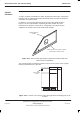
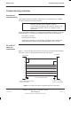
Diagram of TMS airflow Inst. 7–17. . . . . . . . . . . . . . . . . . . . . . . . . . . . . . . . . . . . . . . . . .
Test procedure Inst. 7–18. . . . . . . . . . . . . . . . . . . . . . . . . . . . . . . . . . . . . . . . . . . . . . . . .
Testing the battery backup Inst. 7–19. . . . . . . . . . . . . . . . . . . . . . . . . . . . . . . . . . . . . . . . . . . .
Overview of battery backup test Inst. 7–19. . . . . . . . . . . . . . . . . . . . . . . . . . . . . . . . . .
Battery backup test procedures Inst. 7–19. . . . . . . . . . . . . . . . . . . . . . . . . . . . . . . . . . .
Sample form 1: Request for connection Inst. 7–21. . . . . . . . . . . . . . . . . . . . . . . . . . . . . . . . .
Sample form 2: Completion and inspection form Inst. 7–23. . . . . . . . . . . . . . . . . . . . . . . . .