
Service Manual

GSM-204-423
BTS architectures and interoperability
31st Oct 01
Installation & Configuration: Horizon
macro
outdoor
68P02902W03-A
CONTROLLED INTRODUCTION
Inst. 6–9
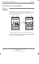
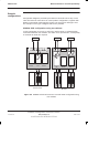
Mixed equipment combining
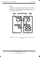
When the two different product types are interfaced, a situation can arise where
a 3IP CBF is connected to an HCU, as shown in Figure 6-8. In this configuration
it is therefore necessary to provide an additional external RF load for this 3IP
CBF. The example in Figure 6-8 shows downlink connections for a 4/4/4
configuration using mixed BTS types.
3IP CBF 2
Load
Load
HCOMB
HCU 2 DDF HCU 1
543 21011109876
2B 1B 0B 2A 1A 0A B A
Sector3 Sector2 Sector1
M-Cell
6
Horizon
macro
3IP CBF 1
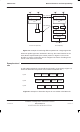
Figure 6-8 Downlink configuration for a 4/4/4 mixed cabinet installation.
Inputs for the DDF are carriers 8 and 9, together with the output of HCU2. The
DDF contains two RF loads and is therefore self-contained. Inputs to 3IP CBF1
are carriers 0 and 1, together with the combined output of HCOMB. 3IP CBF1
contains a single load and is therefore connected to the external load mounted
on HCOMB. Inputs for 3IP CBF2 are carriers 4 and 5, together with the output
of HCU1, from the master cabinet. 3IP CBF2 contains a single load and
therefore requires the addition of an external 50 ohm load, as shown.