
Service Manual

GSM-204-423
BTS architectures and interoperability
31st Oct 01
Installation & Configuration: Horizon
macro
outdoor
68P02902W03-A
CONTROLLED INTRODUCTION
Inst. 6–3
CTU
Horizon
macro
(Extender)
RF coupling
FMUX
Fibre optic link
TCU
RF coupling
MCU
FMUX
Network termination
functions
Cross connections
(see text)
Abis Interface
FOX
M-Cell
6
(Master)
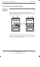
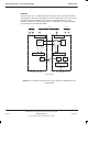
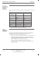
Figure 6-2 Example of interfacing different products at a single logical site
When two product types are interfaced in this way, the control function for the
entire BTS is implemented by the master product. In Figure 6-2, this is the
M-Cell
6
. In practice, either BTS can be configured as master according to the
needs of the network concerned.
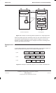
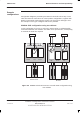
Example mixed
site
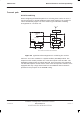
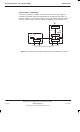
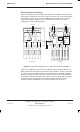
A multi-cabinet mixed site can typically be achieved in several ways. Figure 6-3
shows the alternatives layouts for a four cabinet mixed BTS site.
M-Cell
6
M-Cell
6
M-Cell
6
M-Cell
6
M-Cell
6
M-Cell
6
Layout1
Layout3
Layout2 Horizon
macro
Horizon
macro
Horizon
macro
Horizon
macro
Horizon
macro
Horizon
macro
Figure 6-3 Example of alternative layouts for a 4-cabinet mixed BTS site