
Service Manual


GSM-204-423
Installing batteries in the auxiliary equipment housing
31st Oct 01
Inst. 5–8
Installation & Configuration: Horizon
macro
outdoor
CONTROLLED INTRODUCTION
68P02902W03-A
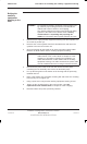
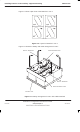
Figure 5-4 show a plan view of the batteries in row 1.
FRONT
+
–
+
–
+
–
+
–
Figure 5-4 Layout for batteries in row 1
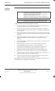
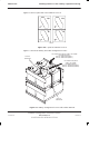
Figure 5-5 shows the battery and cable arrangement in row 1.
FRONT RETAINING PLATE
BATTERY TRAY
REAR RETAINING PLATE
PART No. 3086432N06
PART No. 3086432N07
Figure 5-5 Battery arrangement in row 1 with cables attached