
Service Manual


GSM-204-423
31st Oct 01
Installation & Configuration: Horizon
macro
outdoor
68P02902W03-A
CONTROLLED INTRODUCTION
iii
Chapter 5
Installing the auxiliary equipment housing i. . . . . . . . . . . . . . . . . . . . . .
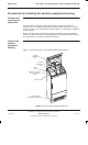
Procedures for installing the auxiliary equipment housing Inst. 5–1. . . . . . . . . . . . . . . . .
Assumptions regarding site preparation Inst. 5–1. . . . . . . . . . . . . . . . . . . . . . . . . . . .
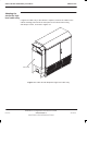
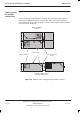
Layout of the auxiliary equipment housing Inst. 5–1. . . . . . . . . . . . . . . . . . . . . . . . .
Auxiliary equipment housing packaging Inst. 5–2. . . . . . . . . . . . . . . . . . . . . . . . . . . .
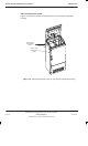
Introduction to installing the auxiliary equipment housing Inst. 5–2. . . . . . . . . . . . .
Installing the auxiliary equipment housing template Inst. 5–3. . . . . . . . . . . . . . . . . .
Installing auxiliary equipment housing bolt anchors Inst. 5–4. . . . . . . . . . . . . . . . . .
Bolting the auxiliary equipment housing to the floor Inst. 5–5. . . . . . . . . . . . . . . . .
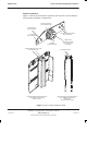
Installing batteries in the auxiliary equipment housing Inst. 5–6. . . . . . . . . . . . . . . . . . . . .
Introduction to battery installation Inst. 5–6. . . . . . . . . . . . . . . . . . . . . . . . . . . . . . . . .
Installing batteries Inst. 5–7. . . . . . . . . . . . . . . . . . . . . . . . . . . . . . . . . . . . . . . . . . . . . .
Auxiliary equipment housing (AEH) connections Inst. 5–10. . . . . . . . . . . . . . . . . . . . . . . . .
Earthing the AEH Inst. 5–10. . . . . . . . . . . . . . . . . . . . . . . . . . . . . . . . . . . . . . . . . . . . . . .
Connecting dc cables to the AEH Inst. 5–10. . . . . . . . . . . . . . . . . . . . . . . . . . . . . . . . .
Connecting the alarm signal cables Inst. 5–11. . . . . . . . . . . . . . . . . . . . . . . . . . . . . . .
Internal connections in the AEH Inst. 5–11. . . . . . . . . . . . . . . . . . . . . . . . . . . . . . . . . .
Configuring battery backup to supply two BTS cabinets Inst. 5–12. . . . . . . . . . . . . . . . . . .
Introduction to configuring battery backup Inst. 5–12. . . . . . . . . . . . . . . . . . . . . . . . . .
Removing the power distribution box Inst. 5–12. . . . . . . . . . . . . . . . . . . . . . . . . . . . . .
Interior view of power distribution box Inst. 5–13. . . . . . . . . . . . . . . . . . . . . . . . . . . . .
Removing the parallelling links Inst. 5–14. . . . . . . . . . . . . . . . . . . . . . . . . . . . . . . . . . . .
Refitting the power distribution box Inst. 5–15. . . . . . . . . . . . . . . . . . . . . . . . . . . . . . . .