
Service Manual


GSM-204-423
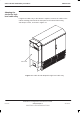
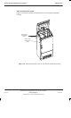
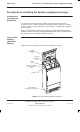
Cable shroud installation procedures
31st Oct 01
Inst. 4–10
Installation & Configuration: Horizon
macro
outdoor
CONTROLLED INTRODUCTION
68P02902W03-A
Cable routeing
for multiple
cabinet sites
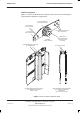
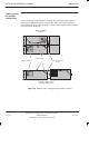
Figure 4-8 shows a representation of the RF interconnection cable routeing
through the cabinets for multiple cabinet sites. FIbre optic interconnections
follow similar routeing. Cable routeing for more complex layouts may be derived
from these basic diagrams.
ÏÏ
ÏÏ
ÏÏ
ÏÏ
ÏÏ
ÏÏÏ
ÏÏÏ
ÏÏÏ
ÏÏÏ
ÏÏÏ
ÏÏ
ÏÏ
ÏÏ
ÏÏ
ÏÏÏ
ÏÏÏ
ÏÏÏ
ÏÏÏ
ÏÏ
ÏÏ
ÏÏ
ÏÏ
ÏÏÏ
ÏÏÏ
ÏÏÏ
ÏÏÏ
ÏÏÏ
CABLE GUIDES
BACK TO BACK
LAYOUT
EXPANSION PLATE
GLAND
SIDE BY SIDE LAYOUT
(left side cable entry)
RF COMPONENTS
Figure 4-8 Guide to cable routeing through multiple cabinets