
Service Manual


GSM-204-423
Cable shroud installation procedures
31st Oct 01
Inst. 4–2
Installation & Configuration: Horizon
macro
outdoor
CONTROLLED INTRODUCTION
68P02902W03-A
Cable shroud installation procedures
Attaching the
cable shroud
frame to the
BTS cabinet
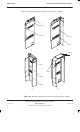
The procedure for attaching the cable shroud frame to the right side of the BTS
cabinet is as follows (letters in parentheses refer to Figure 4-2):
1. Remove the side panels from the cable shroud frame.
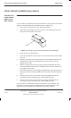
2. Separate the two flanges from the left side of the shroud top panel (see
Figure 4-1) and remove one of them.
FLANGE
Figure 4-1 Shroud top panel detail showing the left hand flanges
3. Open the lid of the BTS cabinet.
4. Screw three M8 bolts loosely into the holes indicated by the arrows STEP
(4) in (A).
5. Slide the rear panel of the shroud onto the rear two bolts and then screw
two M8 bolts into the holes indicated by the arrows STEP (5) in (B).
Tighten all four bolts.
6. Slide the shroud front panel onto the previously installed bolt and then
screw two M8 bolts into the holes indicated by the arrows for STEP (6) in
(C). Tighten all four bolts.
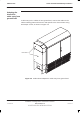
7. Mount the shroud top cover (flanges already fitted) in place and secure to
the cabinet side by inserting an M8 bolt in the position indicated STEP (7)
in (C).
8. Secure the top cover to the shroud rear panel by tightening the two
anti-tamper screws indicated by the arrows STEP (8) in (D).
9. Secure the top cover to the shroud front panel by tightening the two
anti-tamper screws indicated by the arrows STEP (9) in (D).
The procedure for attaching the cable shroud frame is now complete. The
procedures for attaching the shroud side panels are described later in this
chapter and vary according to the method of cable entry required.