
Service Manual


GSM-204-423
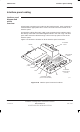
Interface panel cabling
31st Oct 01
Installation & Configuration: Horizon
macro
outdoor
68P02902W03-A
CONTROLLED INTRODUCTION
Inst. 3–67
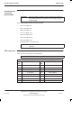
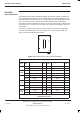
Table 3-12 PIX1 pin connections (37-way D-type)
Pin
no.
Signal/Description Pin
no.
Signal/Description
1 Site input Ext 9–1 19 Not connected
2 Site input Ext 10–1 20 Site input Ext 9–2
3 Site input Ext 11–1 21 Site input Ext 10–2
4 Site input Ext 12–1 22 Site input Ext 11–2
5 Site input Ext 13–1 23 Site input Ext 12–2
6 Site input Ext 14–1 24 Site input Ext 13–2
7 Site input Ext 15–1 25 Site input Ext 14–2
8 Site input Ext 16–1 26 Site input Ext 15–2
9 Not connected 27 Site input Ext 16–2
Pins 10 to 18 not connected Pins 28 to 37 not connected
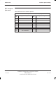
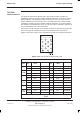
ICS connector
Table 3-13 lists the Integrated Cell Site (ICS) connector pinouts. This is a future
feature.
Table 3-13 ICS pin connections (25-way D-type)
Pin
no.
Signal/Description Pin
no.
Signal/Description
1 ICS0 TTY earth 10 ICS3 TTY earth
2 ICS0 TTY Rx 11 ICS3 TTY Rx
3 ICS0 TTY Tx 12 ICS3 TTY Tx
4 ICS1 TTY earth 13 ICS4 TTY earth
5 ICS1 TTY Rx 14 ICS4 TTY Rx
6 ICS1 TTY Tx 15 ICS4 TTY Tx
7 ICS2 TTY earth 16 ICS5 TTY earth
8 ICS2 TTY Rx 17 ICS5 TTY Rx
9 ICS2 TTY Tx 18 ICS5 TTY Tx
Pins 19 to 25 not connected