
Service Manual


GSM-204-423
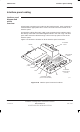
Interface panel cabling
31st Oct 01
Inst. 3–62
Installation & Configuration: Horizon
macro
outdoor
CONTROLLED INTRODUCTION
68P02902W03-A
Interface panel
connector
pinout tables
CAUTION Keep the plastic connector covers (supplied by Motorola)
on unused connectors to protect from damage by static or
foreign matter.
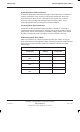
The following tables list the connector pinouts:
GPS, see Table 3-7.
RTC, see Table 3-8.
BIB, see Table 3-9.
T43, see Table 3-10.
PIX0, see Table 3-11.
PIX1, see Table 3-12.
ICS, see Table 3-13.
External alarms, see Table 3-14.
NOTE
Some pin connections only refer to indoor or outdoor
cabinets.
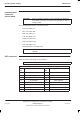
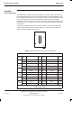
GPS connector
Table 3-7 lists the GPS pin out connections.
NOTE
The GPS connector is optional on later BTS cabinets.
Table 3-7 GPS pin connections (15-way D-type)
Pin
no.
Signal/Description Pin
no.
Signal/Description
1 GPS power 1 9 GPS return 1
2 Rx negative 10 GPS power 2
3 Rx positive 11 PPS positive
4 Tx negative 12 PPS negative
5 Tx positive 13 Not connected
6 Spare (not connected) 14 Not connected
7 VPP (not connected) 15 Not connected
8 GPS return 2