
Service Manual


GSM-204-423
Interface panel cabling
31st Oct 01
Installation & Configuration: Horizon
macro
outdoor
68P02902W03-A
CONTROLLED INTRODUCTION
Inst. 3–61
Interface panel cabling
Interface panel
diagram and
pinout
overview
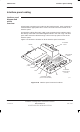
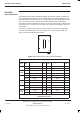
All maincage connectors are located on the interface panel. Each connector is
marked with the appropriate label. Power connectors are also located on the
interface panel.
An extension cabinet fibre optic cable is not connected to the interface panel,
but directly connected to the FMUX digital module in the main cage. The fibre
optic cable enters the cabinet through a hole on the top panel in front of the
interface panel.
Figure 3-36 shows the locations of all the interface panel connectors.
ig.239.rh
T43/BIB
AC POWER
SOCKET INPUT
(not used)
DC POWER
INPUT
GPS
(if fitted)
not used
PIX 0
EXTERNAL ALARMS
(PSU and TMS ALARMS)
PIX 1
ICS
VENTILATION
GRILLE
Figure 3-36 Interface panel connector locations