
Service Manual

GSM-204-423
Connecting antennas
31st Oct 01
Installation & Configuration: Horizon
macro
outdoor
68P02902W03-A
CONTROLLED INTRODUCTION
Inst. 3–33
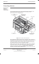
Routeing RF
cables between
cabinets.
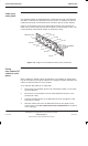
When routeing RF cables between cabinets in Motorola supplied configurations:
1. Remove the expansion plate pass through blanks, as required.
2. Undo the two hose clips securing each RF cable gland housing and
remove gland assembly.
3. Feed any RF cables through the expansion plates.
Refer to Cable shroud installation procedures (Installation between cabinets
and Cable routeing for multiple cabinet sites) in Chapter 4 of this category for
full details of RF gland refitting and shroud installation.
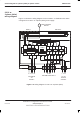
Types of RF
connector
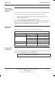
Table 3-2 list the RF module connectors with their destinations.
Table 3-2 RF module connectors and destinations
RF module Type of connector Destination
CTU transceiver SMA Tx block (underneath)
Tx block SMA CTU transceiver
N-type SURF
7/16 Earth/connector plate
SURF N-type Rx N-type of Tx Block
Earth/connector plate 7/16 Antenna or
additional cabinets
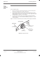
Torque of RF
connectors
For correct torque of connectors, see
Installation & Configuration: GSM-204-423
Chapter 2 Site requirements and considerations.
CAUTION
Care should be taken when tightening SMA connectors to
avoid damage by excessive force.