
Service Manual

GSM-204-423
Connecting antennas
31st Oct 01
Installation & Configuration: Horizon
macro
outdoor
68P02902W03-A
CONTROLLED INTRODUCTION
Inst. 3–31
Connecting antennas
Overview of
antenna
connections
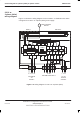
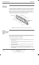
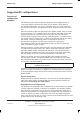
The components shown in Figure 3-10 provide all the RF connections to the
cabinet and internally within the cabinet. Up to four cabinets can be
interconnected to form a single BTS site.
THREE
TRANSMITTER/RECEIVERS
(Tx BLOCKS)
SURF (Rx)
SIX TRANSCEIVERS
(CTUs)
CABLE GUIDES
RIGHT EARTH PLATE
(RF CABLE OMITTED
FOR CLARITY)
BLANK PLATE (LEFT
EARTH PLATE OR
EXPANSION
PLATE OPTIONAL)
Figure 3-10 Location of RF components
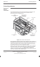
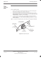
Site configurations supplied by Motorola have appropriate earth, expansion or
blanking plates fitted and all internal RF cables supplied. Antennas need only be
connected to the earth/connector plate as all RF connections internal to the
cabinet, (those between CTUs, Tx blocks, SURF and earth/connector plates),
are cabled correctly for the cabinet configuration supplied.
Multiple cabinet configurations have additional RF cabling, stored, for shipping,
in the master cabinet. These cables will need to be routed to the expansion
cabinets and connected as shown in the Suggested RF configurations
Variations in site layout and RF configuration may require the fitting of left side
cable entry earth plates and/or expansion plates.