
Service Manual


GSM-204-423
Earthing the site
31st Oct 01
Installation & Configuration: Horizon
macro
outdoor
68P02902W03-A
CONTROLLED INTRODUCTION
Inst. 2–13
Earthing the site
Overview
The following provides information on suggested earthing procedures for an
outdoor site.
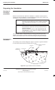
The separate earth systems must be isolated from each other to facilitate
periodic testing of the earth systems. Earth inspection pits are provided for this
purpose.
Earthing
requirements
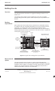
Each cabinet site external earth must be assessed on an individual site basis,
as conditions will vary considerably depending on local soil conditions and site
topography. It is essential that a site survey and soil resistance test be
performed before installation. The site architect defines the site and foundation
earthing requirements to ensure a resistance of less than 10 ohms. A typical site
earthing plan is shown in Figure 2-4.
FOUNDATION
CABINET(S)
COPPER
TAPE
EARTH CONDUCTOR
INTO CABINET VIA
PVC PIPE
CROSS BONDING
MAST BONDING (ONE
SHOWN FOR CLARITY)
FOUNDATION
METALWORK BONDING
FOUNDATION
METALWORK BONDING
FOUR PLACES MINIMUM
FOUNDATION
METALWORK
TEST
CONNECTION
INSPECTION
BOX
EARTH RODS WITH
INSPECTION BOXES FOR
SYSTEM TEST
CROSS
BONDING TEST
CONNECTION
INSPECTION
BOX
MAST
Figure 2-4 Typical site earthing plan for open field site
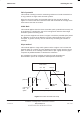
Earth electrode
system
The earth electrode system consists of a series of interconnected earth
electrodes (minimum of four) that are located outside the foundation reinforcing
metalwork. Refer to Figure 2-4 for details. The earth rods should be connected
together using TCO30 solid tape conductors, avoiding any sharp bends; a
minimum bend radius of 250 mm is recommended.