
Service Manual


GSM-204-323
External alarms interface board
31st Oct 01
Tech. 7–4
Technical Description: Horizon
macro
outdoor
CONTROLLED INTRODUCTION
68P02902W02-A
External alarms interface board
Function of the
external alarms
interface board
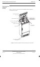
The external alarms interface board is mounted in the power distribution box, in
the lid of the auxiliary equipment housing. It has the following functions:
Provides power to the temperature control equipment in the auxiliary
equipment housing.
Relays alarm signals from the auxiliary equipment housing through the
alarms interface board in the Horizon
macro
outdoor BTS cabinet to the
CAB.
Provides facilities to extend control and alarm functions to a second BTS
cabinet or auxiliary equipment housing.
External alarms
interface board
connections
Power, control and alarm signals are relayed through the external alarms
interface board as described below.
NOTE Cables for connecting the heater mats, fan and
control/alarm signals are extended to the outside of the
power distribution box.
Power connections
External power (–48 V dc) is connected to PL12, pins 1 and 2 on the interface
board via the rear pair of Anderson connectors on the bottom left side of the
power distribution box. If a second BTS cabinet is connected, the supply voltage
is connected to PL12 pins 3 and 4 via the front pair of Anderson connectors.
The fan is powered from PL7. The four heater mats are individually connected
to PL8, PL9, PL10 and PL11.
Control connections
Control signals to trip the circuit breakers in the event of an overtemperature
alarm signal (temperature reaches 65 °C, +/–3 °C) or a low voltage supply
signal (supply voltage drops below 38 V dc).
Alarm connections
The following alarm signals are routed through the interface board to the CAB:
Overtemperature alarm signal (PL1, pins 5 and 6).
Door open signal (PL4).