
Service Manual


GSM-204-323
Temperature control within the auxiliary equipment housing
31st Oct 01
Technical Description: Horizon
macro
outdoor
68P02902W02-A
CONTROLLED INTRODUCTION
Tech. 7–3
Temperature control within the auxiliary equipment housing
Temperature
control
equipment
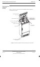
The temperature within the auxiliary equipment housing is regulated by the
following equipment:
A fan, mounted in the lower front panel, to provide cooling and warm air
circulation.
Heater mats, bonded to a metal plate and fitted to the battery trays below
each battery monoblock, to provide heating.
Operation of the
temperature
control
equipment
The fan operates from a –48 V dc supply, connected through PL7 on the
external alarms interface board and protected by a 500 mA anti-surge fuse. The
heater mats each require –48 V dc, connected through PL8, PL9, PL10 and
PL11 for heater mats 1 to 4 respectively on the external alarms interface board.
The supply voltage to each mat is protected by a 5 A fuse.
The 8 W fan operates continually regardless of ambient temperature. The
heater mats operate the ambient temperature is less than 12 °C (+/–3 °C).
The auxiliary equipment housing contains two temperature sensors, providing
sensing for an over temperature alarm and an over temperature trip control
signal.
If the over temperature alarm sensor is triggered (cabinet temperature reaches
55 to 60 °C), this causes an alarm signal to be sent to the OMC-R via the CAB
in the main cabinet. If the over temperature trip sensor is triggered (cabinet
temperature reaches 65 °C, +/–3 °C), the external alarms interface board
disconnects the remote operation circuit breakers, thus removing the supply to
the main cabinet. When the temperature drops to 5 °C below the trip level, the
external alarms interface board causes the circuit breakers to close, thus
restoring the supply to the main cabinet.