
Service Manual


GSM-204-323
Alarm module
31st Oct 01
Technical Description: Horizon
macro
outdoor
68P02902W02-A
CONTROLLED INTRODUCTION
Tech. 6–27
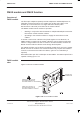
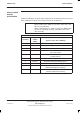
Alarm module
display
presentation
All alarms indicators are green when equipment is functioning correctly, and red
when equipment is faulty. The locations are shown in Table 6-6.
NOTE
Seven of the LEDs are used in the Horizon
macro
outdoor.
LEDs marked red in Table 6-6 are on in alarm state, and
off in normal operation.
LEDs marked bicolour in Table 6-6 (fans) are green when
all fans are operating correctly, and red if one or more
fans are faulty.
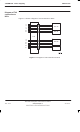
Table 6-6 Alarm module LEDs
LED
location
Light
colour
states
Equipment monitored by light
(Green = OK, Red = FAULT)
1 (top) red AC supply to ac input failed.
2 red Rectifier output failed.
3 red Not used (LED permanently off).
4 red Cabinet door or auxiliary equipment housing
door open alarm.
5 red Low voltage disconnect (LVD) alarm (battery
backup option).
6 bicolour TMS fans fully operational.
7 bicolour Not used (LED permanently green).
8 bicolour Not used (LED permanently green).
9 red TMS 1 failed
(thermal management system).
10 (bottom) red TMS 2 failed
(auxiliary equipment housing).