
Service Manual


GSM-204-323
DDF
31st Oct 01
Technical Description: Horizon
macro
outdoor
68P02902W02-A
CONTROLLED INTRODUCTION
Tech. 5–45
DDF functional
diagram
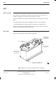
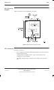
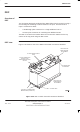
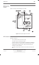
Figure 5-30 shows a functional diagram of the DDF.
Figure 5-30 Functional diagram of the DDF
DDF connectors
Each DDF connects to:
The Tx outputs of three or four CTUs, using:
Two SMA connectors underneath the DDF.
An N-type connector on top of the DDF for connection to a feedthrough
plate (for a third CTU) or HCU plate (for combined third/fourth CTUs).
A single antenna for both Rx and Tx, using a 7/16 connector. This
connector is on top of the DDF.
The SURF, using an N-type connector. This connector is on top of the
DDF.