
Service Manual


GSM-204-323
DCF
31st Oct 01
Tech. 5–42
Technical Description: Horizon
macro
outdoor
CONTROLLED INTRODUCTION
68P02902W02-A
DCF
DCF overview
The purpose of the duplexed combining bandpass filter (DCF) Tx block is to
enable each antenna to serve two CTUs for both Tx and Rx.
The DCF combines two Tx inputs, dissipating half the power within an internal
load.
The signal then passes through a bandpass filter and out to the antenna.
A receive bandpass filter passes only the Rx signal to the SURF module.
The DCF is located in the basket above the CTUs and is attached to the top
surface of the top panel using two M6 screws.
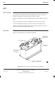
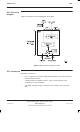
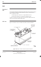
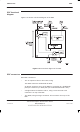
DCF view
Figure 5-27 shows a DCF with connectors identified.
HOLE FOR TOP
PANEL BASKET
ATTACHMENT
N-TYPE CONNECTOR TO
SURF
7/16 CONNECTOR
TO ANTENNA
TWO SMA Tx CONNECTORS
BENEATH DCF (FROM CTU)
HOLE FOR TOP
PANEL BASKET
ATTACHMENT
Figure 5-27 DCF Tx block view with connectors identified