
Service Manual


GSM-204-323
SURF module
31st Oct 01
Tech. 5–26
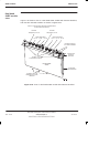
Technical Description: Horizon
macro
outdoor
CONTROLLED INTRODUCTION
68P02902W02-A
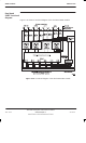
Functional
description of
the single band
SURF
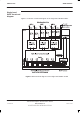
The single band SURF provides front end filtering, amplification, and matrix
control of the RF receive signal between the antenna and the CTU
The single band SURF functional sections (Figure 5-14) consist of loopback,
filtering, amplification, splitting, digital processing and power selection.
Each section is duplicated for the second diversity path except for the digital
and dc power section which is shared by the two diversity paths. There are
three antenna pair inputs (ANT 0, ANT 1 and ANT 2) for each of the two
diversity branches (Branch A and Branch B). There are six outputs to the CTU
for each of the two diversity branches as well as one input from the CTU for the
loopback (LPBK) signal. There is also an output for an expansion cabinet for
ANT 0 on each branch.
The software database must be configured at the OMC-R to accept CTUs of the
same frequency in the appropriate cabinet locations.
The digital section switch, under the control of the database (signalled through
the MCUF and CTUs), routes the six amplifier outputs to the appropriate CTUs.
The digital and power supply section is also responsible for loopback switch
control, manual overrides, alarms and dc voltages.
The RF loopback test function is described in RF overview and RF test
function in this chapter.