
Service Manual


GSM-204-323
CTU frequency hopping
31st Oct 01
Technical Description: Horizon
macro
outdoor
68P02902W02-A
CONTROLLED INTRODUCTION
Tech. 5–23
Transmit
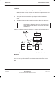
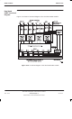
The transmit is described by the following, as shown in Figure 5-12:
1. Traffic data from the network is passed through the NIU to the MCUF.
Within the MCUF an ASIC switches the data to CTU 0 (the dedicated CTU
for this particular MS call example).
2. The CTU, having processed the data (channel coding, interleaving,
encryption and routeing information) then passes the data back to the
ASIC.
3. The ASIC follows the BBH routeing information to direct the data to the
next Tx CTU in the sequence of Table 5-3.
NOTE
BBH differs from normal and SFH CTU Tx procedures, in
that the data is directed to CTUs in a cyclic sequence at
stage 3. Without BBH, stage 3 always routes data to the
original CTU.
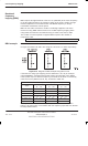
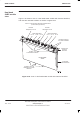
Figure 5-12 shows a schematic diagram of an example of baseband hopping.
Figure 5-12 Schematic of baseband hopping (BBH) example
Receive
Data from the MS is received by one CTU allocated to that MS (in this case
CTU 0). The CTU will synthesize hop to the Rx signal. This ensures that the
handover and equalizers within only one CTU will be connected to a particular
MS.