
Service Manual


GSM-204-323
Compact transceiver unit (CTU)
31st Oct 01
Technical Description: Horizon
macro
outdoor
68P02902W02-A
CONTROLLED INTRODUCTION
Tech. 5–15
Power amplifier board
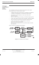
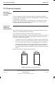
Figure 5-8 shows a functional diagram of the power amplifier (PA). The PA
board provides amplification and a forward power detector. The isolator protects
the PA board amplifiers. The detected output is used to adjust the final CTU RF
power output level by the digital sections of the XCVR.
The PA board consists of six functional blocks:
RF power amplifier.
RF forward power directional coupler.
RF forward power detector.
Temperature sensor.
CCB control.
RF loopback circuit.
The isolator performs two functions:
Isolates multiple transmitters to reduce intermodulation distortion.
Protects the RF power amplifier from possible damage resulting from load
mismatches.
RF FORWARD
POWER
DETECTOR
LOAD
RF OUTPUT
ISOLATOR
RF POWER
AMPLIFIERS
TEMPERATURE
SENSOR
CCB
DATA
INJECT
LOOPBACK
DIRECTIONAL
COUPLER
RF LOOPBACK
DIRECTIONAL
COUPLER
PA BOARD
Figure 5-8 Power amplifier board functional diagram