
Service Manual


GSM-204-323
Compact transceiver unit (CTU)
31st Oct 01
Technical Description: Horizon
macro
outdoor
68P02902W02-A
CONTROLLED INTRODUCTION
Tech. 5–13
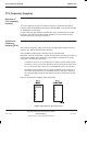
CTU Tx
connector
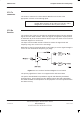
The CTU Tx connector is a short SMA to SMA link to the base of the
appropriate Tx block or feed through plate.
NOTE
The Tx cable has a 90° SMA connector at one end, and a
straight SMA connector at the other end. The 90° end is
designed for connection to the Tx port of a CTU.
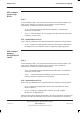
CTU Rx
function
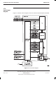
The receiver part of the CTU accepts two amplified and filtered receive antenna
signals from the SURF module. These two signals are applied to inputs (branch
A and branch B) of the CTU transceiver board. Figure 5-5 shows a CTU receiver
functional diagram for one branch.
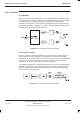
The input from the SURF module is filtered to ensure the signal level and
frequency range are correct for the next stage.
RSSI data is used for Automatic Gain Control (AGC) to ensure signal strength is
correct for the Intermediate Frequency (IF) stage.
Figure 5-5 CTU receiver functional diagram for one branch
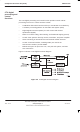
The primary signal flow of the IF is to support traffic and control data.
The path is demodulated into quadrature signals and filtered by baseband
analogue filters. These signals are then digitized (I1/I2 data and Q1/Q2 data)
and made available to the equalizer for the purposes of receive synchronization
and data recovery.