
Service Manual


GSM-204-323
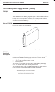
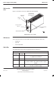
The outdoor power supply module (TOPSM)
31st Oct 01
Technical Description: Horizon
macro
outdoor
68P02902W02-A
CONTROLLED INTRODUCTION
Tech. 4–29
Control and
alarm signals
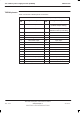
The following signals are associated with TOPSM control and alarms:
Enable out
An independent –55 V output from each TOPSM commoned together and
connected to the normally closed contacts of the disable relay (relay 1), on
the backplane of the power supply unit cage.
Enable in
This signal, fed from the normally closed contacts of the disable relay
(relay 1) on the backplane of the power supply unit cage, enables the
TOPSM output (the relay is operated by the the control and alarm board
under fault conditions).
Voltage trim
A variable voltage signal, generated by the control and alarm board, used
to regulate the TOPSM output in order to produce a temperature
compensated battery charging voltage, to ensure that the internal or
external batteries are not overcharged.
Current share
A signal representing the average current for the total system. Each
TOPSM compares its output current with the average current and adjusts
its output voltage so as to equalize its output current with the average
system current.
Auxiliary supply
A 12 V supply independent of the TOPSM output, but referenced to it,
used to power the control and alarm board circuitry when the TOPSM
output is inhibited.
Input healthy
The normally open contact of the isolated changeover relay used to
indicate that the input is within specification.
Output healthy
The normally closed contact of the isolated changeover relay used to
indicate that the output is within specification.