
Service Manual


GSM-204-323
Control and alarm board (CAB)
31st Oct 01
Technical Description: Horizon
macro
outdoor
68P02902W02-A
CONTROLLED INTRODUCTION
Tech. 4–25
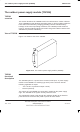
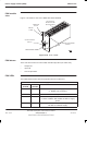
DIP switches
Two of the banks of DIP switches mounted on the CAB circuit board are used to
configure alarm board functions (SW2 and SW4). The location on the board and
exact appearance varies with manufacturer.
SW2 used to inhibit auxiliary equipment housing and optional smoke alarm
signals.
SW4 used to inhibit or set periodicity of automated internal battery
capacity test and to set the CAB into debug mode.
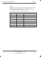
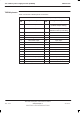
Table 4-4 shows the function of SW2 individual dip switches.
Table 4-4 SW2 DIP switch settings
Switch No Function Position
1 Auxiliary equipment housing over
temperature alarm
ON to inhibit
2 Auxiliary equipment housing over
temperature trip input
ON to inhibit
3 TMS 2 over temperature alarm ON to inhibit
4 Auxiliary equipment housing door
alarm
ON to inhibit
5 TMS 2 fail alarm ON to inhibit
6 BTS cabinet smoke alarm ON to inhibit
7 Auxiliary equipment housing smoke
alarm
ON to inhibit
8 Internal/external battery temperature
sensing
ON for internal
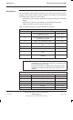
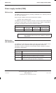
Table 4-5 shows the function of SW4 individual dip switches.
NOTE
If more than one switch is selected, delay timing is
cumulative up to a maximum of 30 days. If no switches are
set, the delay period is 1 day.
By default, the CAB is configured with automated battery
capacity test inhibited and the delay DIP switches set to
30 days.
Table 4-5 SW4 DIP switch settings
Switch No Function Position
1 2 day delay setting OFF to select
2 4 day delay setting OFF to select
3 8 day delay setting OFF to select
4 16 day delay setting OFF to select
5 Debug OFF to select
6 Automated battery capacity test inhibit ON to select