
Service Manual


GSM-204-323
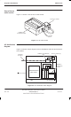
DC power distribution
31st Oct 01
Tech. 4–12
Technical Description: Horizon
macro
outdoor
CONTROLLED INTRODUCTION
68P02902W02-A
Internal battery
arrangement
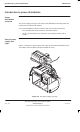
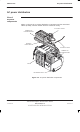
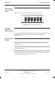
Figure 4-12 shows how the batteries are arranged in the battery tray.
BATTERY 1
BATTERY 2
BATTERY 3
BATTERY 4
Figure 4-12 Internal battery arrangement in the battery tray
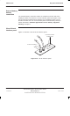
View of battery
sense lead
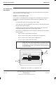
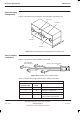
Figure 4-13 show the internal battery sense lead.
M6 INSULATED
RING TERMINALS
MOLEX 4 WAY CONNECTOR
Figure 4-13 Battery sense lead assembly
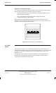
Table 4-1 details the wiring schedule of the battery sense lead.
Table 4-1 Battery sense lead to Molex connector
Molex
connector pin
Terminal
ident
Location
1 C Battery 1 –ve terminal
2 B Battery 2 –ve terminal
3 D Battery 3 –ve terminal
4 E Battery 4 –ve terminal at
circuit breaker top terminal