
Service Manual


GSM-204-323
DC power distribution
31st Oct 01
Technical Description: Horizon
macro
outdoor
68P02902W02-A
CONTROLLED INTRODUCTION
Tech. 4–11
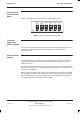
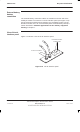
View of the dc
circuit breaker
panel
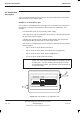
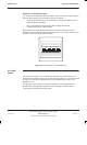
Figure 4-11 shows a front view of the dc circuit breaker panel.
EXT
BATT
TMS
FANS
COMMS
1
80 A10 A5 A5 A5 A5 A
COMMS
2
COMMS
3
COMMS
4
Figure 4-11 The dc circuit breaker panel
Customer
equipment
power supplies
The four power outlets mounted adjacent to the customer equipment racks are
supplied from the multilayer busbar by individual 5 A circuit breakers,
(see Figure 4-11).
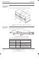
Internal battery
backup
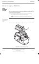
The internal battery tray, located at the lower right side of the PSU, holds four
12 V batteries connected in series to provide a total output of 48 V dc, with a
capacity of 15 Ah.
The internal batteries are protected by an 80 A circuit breaker, mounted on the
battery tray front panel. The circuit breaker also functions as a disconnect switch
for the internal batteries.
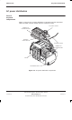
Battery voltage sensing leads are fed from the negative terminal of each battery
to a four way connector on the battery tray. This is connected to the control and
alarm board (CAB). The sensed voltages are used by the battery capacity test
and battery selector switch functions of the CAB.