
Service Manual


GSM-204-323
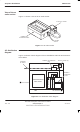
DC power distribution
31st Oct 01
Tech. 4–10
Technical Description: Horizon
macro
outdoor
CONTROLLED INTRODUCTION
68P02902W02-A
DC distribution
diagram
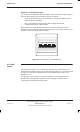
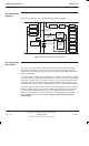
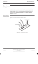
Figure 4-10 shows the –55 V dc distribution as a block diagram.
SURF
BPSMS
CBM
TMS FANS
CTU
CTU
CTU
CTU
CTU
CTU
COMMS
EQUIPMENT
EXTERNAL
BATTERY
CABINET
COMMS
CONTACTOR
PSM
(DC/DC conv)
TOPSM
INTERNAL
BATTERIES
TOPSM
TOPSM
BATT
CONTACTOR
0 V dc
–55 V dc
Figure 4-10 DC distribution block diagram
DC distribution
description
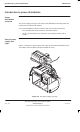
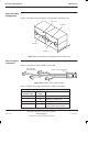
The main cage dc supply is routed from the left side of the multilayer busbar
through the dc interface panel (see Figure 4-14) to the main cage interface
panel. Circuit protection for the main cage is provided by the CBM and internal
fusing in the PSMs.
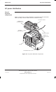
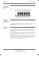
The other circuits supplied from the multilayer busbar are protected by individual
circuit breakers. Six of the circuit breakers are mounted on the dc circuit breaker
panel of the outdoor PSU, as shown in Figure 4-11. The internal batteries have
a separate 80 A circuit breaker, housed within the battery mounting tray. The
circuit breakers also function as switched disconnects for their respective loads.
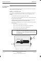
The PSU cage has two contactors as part of the dc distribution system. During
periods of battery back-up, the contactors will progressively disconnect battery
loads as battery voltage decreases, to prevent deep discharge of backup
batteries. The operation of these contactors is controlled by the control and
alarm board and is described in detail in Outdoor PSU control and alarm
board (CAB)