
Service Manual


GSM-204-323
Power supply enclosure
31st Oct 01
Tech. 2–18
Technical Description: Horizon
macro
outdoor
CONTROLLED INTRODUCTION
68P02902W02-A
TMS test
switches
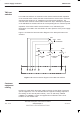
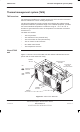
Four TMS test switches are mounted on the alarms interface board. Operation
of the override switch causes the TMS control board to set the fans to minimum
speed and the heaters to off, regardless of environmental conditions. The
override switch must be held to enable further test steps. Subsequent operation
of the individual fan switches will set the corresponding fans to maximum speed.
Operation of the heater switch sets the heaters to on, indicated by the
illumination of an LED in the recirculation air return aperture of the power supply
enclosure.
Figure 2-14 shows the interconnection diagram of the TMS push button test
switches.
HEATER
ON
N/O
N/O
N/O
N/O
TEST
OVERRIDE
Pole
SW4SW3
SW2
Pole
PolePole
SW1
11 13 15 10 12
14
PL5
9
INTERNAL
FANS
EXTERNAL
FANS
Figure 2-14 Interconnection diagram of the TMS test switches
Customer
equipment
racking
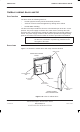
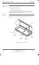
Provision is made within the power supply enclosure for the fitting of customer
specific equipment, in 6 U of standard 19 inch equipment racking. Adjacent to
the racking are four 125 W power outlets (– 55 V dc and earth), labelled
COMMS 1 to COMMS 4. These are supplied from individual 5 A dc circuit
breakers on the outdoor PSU.