
Service Manual

GSM-204-323
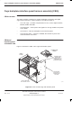
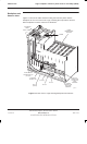
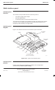
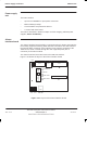
Power supply enclosure
31st Oct 01
Technical Description: Horizon
macro
outdoor
68P02902W02-A
CONTROLLED INTRODUCTION
Tech. 2–17
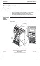
Alarms
interface board
connectors
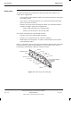
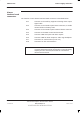
The function of each alarms interface board connector is described below:
PL1 Connects to the auxiliary equipment housing alarm output
signal cable.
PL2 Connects to the interface panel PIX0 connector, to enable
remote initiation of battery tests.
PL3 Connects to the interface panel external alarms connector.
PL4 Connects to the PSU control interface board.
PL5 Connects TMS test inputs and alarm outputs.
PL6 Connects TMS fan alarm outputs to main cage backplane.
PL7 Connector for smoke alarms (not in use).
PL8 Connector for door microswitches.
NOTE
PIX0 connector PL2 is normally disconnected and stowed.
If remote initiation/reporting functionality of internal battery
capacity test is to be used, PL2 must be connected to
alarms interface board.