
User's Manual Part 2

Alarms Testing – continued
08/01/2001
3-89
1X SCt4812ET Lite BTS Optimization/ATP
PRELIMINARY
Single Rectifier Failure
(Four Rectifier System)
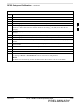
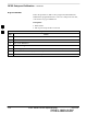
Table 3-54 gives instructions on testing single rectifier failure or minor
alarm in a four (4) rectifier system (two–carrier system).
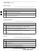
Table 3-54: Single Rectifier Fail or Minor Alarm, Two–Carrier System
Step Action
1
! CAUTION
Only perform this test if the rectifier current load displayed on the AMP indicator on the MAP is
125 amps or less. Sufficient current capability to support a greater load may not be available when
two rectifiers are removed from the bus in the following steps.
Unseat the rectifier in shelf position 4 from its connection at the rear of the shelf, but do not
completely remove it from the shelf.
S The rectifier 4 DC and PWR LEDs may light red momentarily and extinguish. There should be no
other indications on the frame or CDMA LMF.
2 On the ACLC, set the RECT. 2/4 circuit breaker to OFF.
S The rectifier 2 DC and PWR LEDs should light red.
S The MINOR ALARM (amber) and RECTIFIER FAIL (red) LEDs on the MAP should light.
S The CDMA LMF should report an alarm condition as BTS Relay #21 and BTS Relay #24
contacts, respectively.
3 Re–seat the rectifier in shelf position 4 into its connection at the rear of the shelf.
4 On the ACLC, set the RECT. 2/4 circuit breaker to ON.
S The rectifier DC and PWR LEDs should light green.
S All alarm indications should clear on the rectifiers, MAP, and CDMA LMF.
3