SCt4812ET RF and Power Cabinet Hardware Installation Manual System Software Release 2.16.
800/1700/1900 MHz CDMA English Apr 2001 68P09253A94–1 SCt4812ET RF and Power Cabinet Hardware Installation Manual
SCt4812ET RF and Power Cabinet Hardware Installation Manual System Software Release 2.16.
Notice While reasonable efforts have been made to assure the accuracy of this document, Motorola, Inc. assumes no liability resulting from any inaccuracies or omissions in this document, or from use of the information obtained herein. The information in this document has been carefully checked and is believed to be entirely reliable. However, no responsibility is assumed for inaccuracies or omissions. Motorola, Inc.
Table of Contents SCTM 4812ET RF and Power Cabinet Hardware Installation Manual Release 2.16.0 This manual includes... Chapter Version Description Front V00.04 Foreword, General Safety, Revision History, Patent Notification 3 1 V01.03 Introduction 13 2 V02.03 Site Preparation 33 3 V03.03 How to Unpack the SC 4812ET BTS 59 4 V04.03 Cabinet Mounting 67 5 V05.03 Cabinet Cabling 81 6 V06.03 What’s Next and Cleanup 119 A V0A.03 Installing RGPS 123 B VOB.
Foreword Scope of manual This manual is intended for use by cellular telephone system craftspersons in the day-to-day operation of Motorola cellular system equipment and ancillary devices. It is assumed that the user of this information has a general understanding of telephony, as used in the operation of the Public Switched Telephone Network (PSTN), and is familiar with these concepts as they are applied in the cellular mobile/portable radiotelephone environment.
Foreword – continued The following typographical conventions are used for the presentation of software information: S In text, sans serif BOLDFACE CAPITAL characters (a type style without angular strokes: i.e., SERIF versus SANS SERIF) are used to name a command. S In text, typewriter style characters represent prompts and the system output as displayed on an operator terminal or printer.
Foreword – continued Reporting manual errors In the event that you locate an error or identify a deficiency in your manual, please take time to write to us at the address above. Be sure to include your name and address, the complete manual title and part number (located on the manual spine, cover, or title page), the page number (found at the bottom of each page) where the error is located, and any comments you may have regarding what you have found. We appreciate any comments from the users of our manuals.
General Safety Remember! . . . Safety depends on you!! The following general safety precautions must be observed during all phases of operation, service, and repair of the equipment described in this manual. Failure to comply with these precautions or with specific warnings elsewhere in this manual violates safety standards of design, manufacture, and intended use of the equipment. Motorola, Inc. assumes no liability for the customer’s failure to comply with these requirements.
General Safety – continued Dangerous procedure warnings Warnings, such as the example below, precede potentially dangerous procedures throughout this manual. Instructions contained in the warnings must be followed. You should also employ all other safety precautions that you deem necessary for the operation of the equipment in your operating environment. WARNING Dangerous voltages, capable of causing death, are present in this equipment. Use extreme caution when handling, testing, and adjusting .
Revision History Manual Number 68P09253A94 Manual Title SCTM 4812ET RF and Power Cabinet Hardware Installation Manual Version Information The following table lists the manual version, date of version, and remarks on the version. Version Level Date of Issue 1 Apr 2001 Apr 2001 V00.
Patent Notification Patent numbers This product is manufactured and/or operated under one or more of the following patents and other patents pending: 4128740 4193036 4237534 4268722 4282493 4301531 4302845 4312074 4350958 4354248 4367443 4369516 4369520 4369522 4375622 4485486 4491972 4517561 4519096 4549311 4550426 4564821 4573017 4581602 4590473 4591851 4616314 4636791 4644351 4646038 4649543 4654655 4654867 12 4661790 4667172 4672657 4694484 4696027 4704734 4709344 4710724 4726050 4729531 4737978 474
1 Chapter 1: Introduction This section includes... Apr 2001 V02.03 Product Description . . . . . . . . . . . . . . . . . . . . . . . . . . . . . . . . . . Scope of this Document . . . . . . . . . . . . . . . . . . . . . . . . . . . . . . . 14 14 Manual Overview . . . . . . . . . . . . . . . . . . . . . . . . . . . . . . . . . . . . Recommended Documents . . . . . . . . . . . . . . . . . . . . . . . . . . . . . Acronyms . . . . . . . . . . . . . . . . . . . . . . . . . . . . . . . . . . . . . . . . . .
1 Introduction – continued Product Description The SC 4812ET BTS consists of an RF Cabinet that is an outdoor, weatherized version of the SC 4812T. The RF cabinet is powered by 27 VDC and each cabinet has the capability to support up to 4 carriers (at 3 sector) or 2 carriers (at 6 sector). An optional outdoor, weatherized Power Cabinet that provides AC/DC rectified power and battery back–up is also available.
Introduction – continued Chapter 4 – “Cabinet Mounting” – This chapter covers cabinet preparation, rooftop (elevated) and concrete pad mounting, and battery installation. Chapter 5 – “Cabinet Cabling” – This chapter contains procedures for cabling the RF and Power Cabinet. This includes earth ground, alarm & span line, RGPS, RF GPS, LFR, RF, AC power, DC power, and other cabling considerations. Chapter 6 – “What’s Next and Cleanup” – This chapter includes site cleanup and a pre–optimization checklist.
1 Introduction – continued S Site Document (generated by Motorola Systems Engineering) which includes: – trial specific documentation – channel allocation – contact list (customer) – ancillary/expendable equipment list – site wiring lists – card placement – contact list (Motorola support) – job box inventory S Demarcation Document (Scope of Work agreement) S Grounding Guidelines for Cellular Radio Installations (Motorola part number 68P81150E62) S Installation manuals for non-Motorola equipment (for ref
Introduction – continued Table 1-1: Acronyms Acronym EMPC6 ETIB FRU GLI2 GPS GFCI HSO HSOX IIP3 ISB LAPD LAN LPA LPAC LFR LMF MCC–1X MMI MPC MGB OSP PB PCSC PSTN PN POTS PS RGD RGPS RFDS RX SS SAPB STLPA STRAU TCH Apr 2001 V02.
1 Introduction – continued Installation Hardware Table 1-2 shows the quantity and description of the installation hardware that is shipped with the RF Cabinet and with the Power Cabinet. Figure 1-1 is a template guide for identifying the parts.
Introduction – continued Figure 1-1: SC 4812ET Installation Hardware M12 X 30 BOLT 5/8” FLAT WASHER LARGE FLAT WASHER 5/8” BOLT M12 NUT M12 FLAT WASHER INSULATION SHOULDER WASHER WEATHERSEAL BUSHING & NUT M10 NUT M12 X 100 M10 FLAT WASHER M6 NYLON LOCKING NUT M12 LOCK WASHER M6 FLAT WASHER FW00468 COMPRESSION LUG (FOR #2 AWG GROUND WIRE) Apr 2001 V02.
1 Introduction – continued Recommended Tools Table 1-3 lists tools recommended for installing RF and Power Cabinets.
Introduction – continued Materials Available from Motorola Table 1-4 lists tools and materials available from Motorola. The items are identified by the Motorola assigned part number and include a brief description. These items can be ordered from your sales account team.
1 Introduction – continued Overview The major components which make up the Motorola SC 4812ET RF Cabinet (see Figure 1-2) and Power Cabinet (see Figure 1-7) system are illustrated in this section. CAUTION A service tent [reference: Pelsue Cabinet Mounted Service Tent; Pelsue (800–525–8460) P/N CM564866M] must be in place prior to opening the main doors of the SC 4812ET RF or Power Cabinet during times of inclement weather (rain, snow, sleet, or hail).
Introduction – continued RF Cabinet External FRUs Figure 1-3 shows the location of the External Field Replaceable Units in the RF Cabinet. A brief description of each External FRU is found in the following paragraphs. Figure 1-3: RF Cabinet External FRUs External Blower Assembly (EBA) Note: LPA Compartment door not shown for clarity LPA Unpopulated LPA Shelf Cover FW00190 Linear Power Amplifier (LPA) The LPA (See Figure 1-4) amplifies RF signals for transmission via the antenna.
1 Introduction – continued External Blower Assembly (EBA) The External Blower Assembly (see Figure 1-5) is a modular unit that provides cooling to the LPA’s, two blowers are used in the RF Cabinet. CAUTION The EBA contains two blowers and provides cooling that is VITAL to prevent service outage and possible damage to the LPAs. Since the SC 4812ET can continue to operate normally with one functional blower in the EBA, the EBA should not be removed until the replacement EBA is onsite.
Introduction – continued RF Cabinet Internal FRUs Figure 1-6 shows the location of the Internal Field Replaceable Units. A brief description of each Internal FRU is found in the following paragraphs. Figure 1-6: RF Cabinet Internal FRUs EBA ETIB CCP Fans RFDS C–CCP Shelf 5 RU Rack Space Combiner Cage OPTIONAL AREA DC Power Dist.
1 Introduction – continued Combiner Cage (2:1, 4:1, or Band pass Filter) The Combiner Cage holds the transmit band pass filters, 2:1 combiners, or 4:1 combiners, depending on system configuration. Combined CDMA Channel Processor (C–CCP) Shelf The C–CCP shelf contains the following: S High Stability Oscillator (HSO)/LFR (Optional) card S Clock Synchronization Manager (CSM) on 2 cards (one with GPS S S S S S S S S S S S S receiver if ordered).
Introduction – continued Heat Exchanger The Heat Exchanger provides cooling to the internal compartment of the RF Cabinet. The fan speed of the heat exchangers adjusts automatically with temperature. The Heat Exchanger is located in the primary front door of the RF Cabinet. Power Cabinet Figure 1-7 illustrates the Power Cabinet design. Figure 1-7: Power Cabinet GFCI Outlet Cover Battery Door Rear I/O Door Rear DC Conduit Panel Main Door Rear AC Conduit Panel FW00193 Apr 2001 V02.
1 Introduction – continued Power Cabinet Internal FRUs Figure 1-8 shows the location of the Internal Field Replaceable Units. The FRUs are described in the following paragraphs. Figure 1-8: Power Cabinet with Batteries Installed (Doors Removed for Clarity) Rectifier Alarm Module Temperature Control Module Rectifier Shelves Batteries (Battery Heaters located under batteries) AC Outlet Cover NOTE Punch Block is not visible in this view.
Introduction – continued Battery Compartment Fan The battery compartment fan provides air circulation for the two battery compartments. It is located on the inside of the battery compartment door. Heat Exchanger The Heat Exchanger provides cooling to the rectifier compartment of the Power Cabinet. The Heat Exchanger is located in the primary front door of the Power Cabinet.
1 Introduction – continued Enclosure Clearances Figure 1-9 and Figure 1-10 show the clearances for the SC 4812ET RF and Power Cabinet enclosures. Figure 1-9: Minimum Cabinet Clearances for Door Openings and Mounting Brackets 0mm (0I) 130mm (5I) 1550mm (61I) 1880mm (74I) 0mm (0I) 660mm (26I) Power Cabinet 1372mm (54”) 1651mm (65I) 2515mm (99I) 0mm (0I) NOTE Not To Scale 510mm (20I) RF Cabinet 1220mm (48”) 1421mm (56I) 2363m (93I) 0mm (0I) 255mm (10I) 1676mm (66I) 1803mm (71I) FW00104 . . .
Introduction – continued Figure 1-10: Minimum Site Clearances for SC 4812ET Cabinets 130 mm (5”) 1143 mm (45”) Power Cabinet 660 mm (26”) 330 – 610 mm (13” – 24”) 3430 – 3710 mm (135 – 146”) RF Cabinet 660 mm (26”) 1143 mm (45”) 2515 mm (99”) 130 mm (5”) FW00105 NOTE: (1) 24” IS RECOMMENDED BETWEEN CABINETS TO ALLOW SIMULTANEOUS OPENING OF CABINET DOORS (2) BASED ON FIGURE 1–10 MOTOROLA RECOMMENDS A MINIMUM PAD (OR PEDESTAL) SIZE OF 2515 MM (99”) BY 3710 MM (146”) Apr 2001 V02.
1 Introduction – continued Notes 32 SCTM 4812ET RF and Power Cabinet Hardware Installation Manual DRAFT Apr 2001 V02.
2 Chapter 2: Site Preparation This section includes... Overview . . . . . . . . . . . . . . . . . . . . . . . . . . . . . . . . . . . . . . . . . . . Indoor Location . . . . . . . . . . . . . . . . . . . . . . . . . . . . . . . . . . . . . Rooftop Location . . . . . . . . . . . . . . . . . . . . . . . . . . . . . . . . . . . . Cabinet Weight Table . . . . . . . . . . . . . . . . . . . . . . . . . . . . . . . . . SC 4812ET RF Configuration . . . . . . . . . . . . . . . . . . . . . . . . . .
Site Preparation – continued Figure 2-3: Grounding Ring Detail . . . . . . . . . . . . . . . . . . . . . . Figure 2-4: Conduit Stub Height Detail . . . . . . . . . . . . . . . . . . . Figure 2-5: Cabinet Dimensions . . . . . . . . . . . . . . . . . . . . . . . . . Figure 2-6: Pad Forms and Conduit Layout . . . . . . . . . . . . . . . . Figure 2-7: Mounting Hole Dimensions . . . . . . . . . . . . . . . . . . . Figure 2-8: SC 4812ET RF Cabinet Conduit I/O . . . . . . . . . . . .
Site Preparation – continued – Adequate ventilation must be available to dissipate heat loads of 7,500 Watts (25,600 Btu / hr) for the RF Cabinet and 3,000 Watts (10,300 Btu / hr) for the Power Cabinet (a total of 10,500 Watts; 35,900 Btu / hr), and maintain a maximum temperature of no greater than 50 Deg C (122 Deg F). – The AC meter and main disconnect should not be mounted to either cabinet. – Locations should be selected that will minimize accidental or intentional vandalism.
Site Preparation – continued Rooftop Location In addition to the Indoor location considerations, the following additional items should be considered when choosing a Rooftop location: 2 WARNING Roof load carrying limits must be reviewed and an appropriate support structure must be installed to support the cabinets as required. CAUTION The cabinets must be elevated sufficiently above the roof surface to prevent water from puddling around its base.
Site Preparation – continued Table 2-2: Approximate Weight of SC 4812ET BTS # of Sectors – Carriers1 3 6 9 12 RF Cabinet2 Power Cabinet3 2 Total Weight Weight/Area Total Weight Weight/Area 570 kg (1260 lbs) 610 kg (1340 lbs) 644 kg (1420 lbs) 680 kg (1500 lbs) 563 kg/m2 (0.8 psi) 602 kg/m2 (0.85 psi) 636 kg/m2 (0.91 psi) 671 kg/m2 (0.95 psi) 1015 kg (2240 lbs) 1206 kg (2660 lbs) 1400 kg (3080 lbs) 1590 kg (3500 lbs) 1002 kg/m2 (1.84 psi) 1192 kg/m2 (1.7 psi) 1383 kg/m2 (2.0 psi) 1571 kg/m2 (2.
Site Preparation – continued Table 2-3: SC 4812ET FRU Configurations – Duplexed BTS 1 – Starter Con– fig Ttl # Sec Car VH LPAs Trnk Mod 4812 DBPF 4812 2:1 Cmbr BTS 2 – Expansion 4812 4:1 Cmbr DRDCs Dplxd Ants VH LPAs Trnk Mod 4812 DBPF 4812 2:1 Cmbr 4812 4:1 Cmbr DRDCs Dplxd Ants Expansion Field Recabling Expansion Impact to Service 3 Sector 1 car 3 4 1 3 3 opt 3 opt 6 6 2 car 6 8 2 3 3 opt 3 opt 6 6 Add Tx cable trunking module to DBPF/conbiner.
Site Preparation – continued Table 2-3: SC 4812ET FRU Configurations – Duplexed BTS 1 – Starter Con– fig Ttl # Sec Car VH LPAs Trnk Mod 8 car 24 16 4 car 24 16 BTS 2 – Expansion 4812 DBPF 4812 2:1 Cmbr 4812 4:1 Cmbr DRDCs Dplxd Ants VH LPAs Trnk Mod 4812 DBPF 4812 2:1 Cmbr 4812 4:1 Cmbr DRDCs Dplxd Ants 4 NA NA 3 6 (3 opt) 3 16 4 NA 3 3 3 3 Add Tx cable trunking module to combiner 4 NA 6 NA 12(6– opt) 6 16 4 NA 6 NA 6 6 Add Tx cable trunking module to combin
Site Preparation – continued Table 2-4: SC 4812ET FRU Configurations – Non–Duplexed BTS 1 – Starter Con– fig Ttl # Sec Car VH LPAs Trnk Mod 4812 DBPF 4812 2:1 Cmbr BTS 2 – Expansion 4812 4:1 Cmbr TRDCs VH LPAs Trnk Mod 4812 DBPF 4812 2:1 Cmbr 4812 4:1 Cmbr RX Ant TX Ant 3 3 (6 opt) 4 1 3 3 opt 3 opt 3 3 TRDCs RX Ant Expansion Field Recabling Expansion Impact to Service 3 Recable Starter Tx to add combiners, recable Starter Rx, cable Rx exp.
Site Preparation – continued Table 2-4: SC 4812ET FRU Configurations – Non–Duplexed BTS 1 – Starter Con– fig Ttl # Sec Car VH LPAs Trnk Mod 8 car 24 16 4 BTS 2 – Expansion 4812 DBPF 4812 2:1 Cmbr 4812 4:1 Cmbr TRDCs RX Ant TX Ant VH LPAs Trnk Mod 4812 DBPF 4812 2:1 Cmbr 4812 4:1 Cmbr TRDCs RX Ant TX Ant NA NA 3 6 (3 opt) 3 3 (6 opt) 16 4 NA 3 3 3 3 3 Expansion Field Recabling Expansion Impact to Service Add Tx cable trunking module to combiner None NOTES: Tx combiner
Site Preparation – continued 2 Minimum Battery Count for Power Cabinet Table 2-5 lists the number of Battery strings required for the different sector–carrier configurations and the backup power time provide by the various combinations. Table 2-5: Minimum Battery Strings Required for Sector–Carrier Configurations # of Battery Strings 3 Rectifiers (3 Sector–Carriers) 4 Rectifiers (6 Sector–Carriers) 5 Rectifiers (9 Sector–Carriers) 6 Rectifiers (12 Sector–Carriers) 0 0 0 0 4.0 hrs 4.8 hrs 5.
Site Preparation – continued In addition to the Indoor location considerations, the following additional items should be considered when choosing an outdoor location: – The cabinet should be placed in a location with appropriate clearance from any obstructions. For minimum clearances see Chapter 1. – It should be the practice of any installing company to acquire, in advance of construction, the rights of way from landowners, and permits or approvals from public authorities.
Site Preparation – continued NOTE It may not be necessary or desirable to run the transmission lines in any conduit at all. In this case the transmission lines should be protected from falling objects (i.e., ice, etc.) or from being stepped on. 2 Table 2-6: Heliax Cable Loss and Minimum Bend Radii dB loss per meter dB loss per foot Min. bend radius Heliax Cable Motorola Part No. @ 1 GHz @ 2 GHz @ 1 GHz @ 2 GHz Metric U.S.
Site Preparation – continued IMPORTANT * The Power Cabinet is rated at 130 Amps (100 Amps continuous / 130 Amps non–continuous, in the range of 208–240V AC, see Table 5-32 for details). Maximum cable size that can be accommodated is 300 kc mil. Cabling sizing should be determined by Local Electrical Codes, using 90Deg C rated conductors, and derated for 50 Deg C operation.
Site Preparation – continued Power Cabinet Alarm Cable – A Twelve (12) wire, Six (6) twisted pair cable [Cable supplied with the Power Cabinet is 4.5 m (15 ft) in length]. 2 NOTE Custom cable lengths are available from Storm Products (214–637–1381); 9215 Premier Row, Dallas, TX. 75247. Part number “070197–6SA” for Non–Plenum rated cable.
Site Preparation – continued Drilling Introduction The following includes steps that must be followed to safely drill the mounting holes. Check the mounting hardware to be used to make sure you use the correct drill bit sizes. 2 CAUTION Motorola recommended anchor bolts (Motorola P/N CGDS97400036) must be used to assure safety in the event of an earthquake.
Site Preparation – continued Table 2-8: Drilling Procedure Step Action 2 Position the end of the drill bit in the center of the first mark on the floor. Stabilize the drill by holding the drill handle at the 90_ position, refer to Figure 2-1. Rest the drill against your leg while drilling to counter the drill’s tendency of rotating out of your hand while drilling through reinforcement bars and stone aggregate.
Site Preparation – continued Table 2-8: Drilling Procedure Step Action 4 Have a second installer turn on the shop vacuum and place the nozzle near the hole to collect dust and debris (see Figure 2-2). This will extend the life of the drill bit, and give you a better idea of how deep the hole is. Wrapping a piece of electrical tape around the drill bit to indicate the desired depth is suggested.
Site Preparation – continued Refer to Figure 2-5 and Figure 2-6 for proper position of mounting locations when designing the support structure. For most rooftop installations all of the connections to the cabinet will be made through the rear of the cabinet I/O area. For this reason, the cabinet must be set in place and bolted down prior to running any conduits or wiring. Conduit/wire routing will be discussed in Chapter 5. 2 Lightning protection is included in the cabinet.
Site Preparation – continued CAUTION Conduits that are pre–installed in a concrete pad below grade must be capped at the time of conduit installation to prevent rainwater from collecting in the conduit. 2 WARNING If a precast concrete foundation pad is used, the pad should be in place before the cables are installed. This will avoid an unsafe condition caused by personnel reaching under a pad, as it is lowered, to feed cable through the pad openings.
Site Preparation – continued Installation Procedure: Install the concrete pad and ground system as described in Table 2-9. 2 Table 2-9: Concrete Pad and Ground System Installation Procedure Step Action 1 Ensure that the pad location is firm and level. If the ground around the location is not firm, compact the soil and construct a level base for the pad using a minimum of six inches of gravel or per local code requirements.
Site Preparation – continued Grounding Ring: The following information details installation of the site grounding ring. Refer to Figure 2-3 for detail dimensions.
Site Preparation – continued Figure 2-5: Cabinet Dimensions 2 605 mm (24”) 102 mm (4”) POWER CABINET 711 mm (28”) 365 mm (15”) 1030 mm (41”) 1425 mm (56”) 102 mm (4”) 455 mm (18”) 711 mm (28”) 270 mm (11”) RF CABINET 341 mm (14”) 1060 mm (42”) 205 mm (8”) 54 1425 mm (56”) FW00106 SCTM 4812ET RF and Power Cabinet Hardware Installation Manual DRAFT Apr 2001
Site Preparation – continued 1471 mm 1518 mm (57.9”) (59.8”) 1091 mm (42.9”) 527 mm (20.7”) 587 mm (23”) 145 mm (5.7”) 49 mm (1.9”) 89 mm (3.5”) 0 1188 mm (46.7”) 1289 mm 1390 mm (50.7”) (54”) 1470 mm 1518 mm (57.9”) (59.8”) 0 49 mm (1.9”) 867 mm (34.2”) 973 mm 1158 mm (38.3) (45.6”) Figure 2-6: Pad Forms and Conduit Layout 61 mm (2.4”) –65 mm (–2.5”) 5 mm (0.2”) 0 0 16 mm (0.6”) 87 mm (3.4”) 475 mm (18.7”) 614 mm (24.2”) 2 14 mm (0.
Site Preparation – continued Figure 2-8: SC 4812ET RF Cabinet Conduit I/O 2 75 mm (3.0”) 629 mm (24.7”) 650 mm (25.5”) 595 mm (23.4”) 415 mm (16.3”) 340 mm (13.3”) 469 mm (18.5”) 211 mm (8.3”) 104 mm (4.1”) 0 mm (0”) 67 mm (2.6”) 0 mm (0”) 65 mm (2.6”) 1069 mm (42.1”) 0 mm (0”) 56 139 mm (5.4”) 65 mm (2.6”) 261 mm (10.3”) 70 mm (2.8”) 587 mm (23.1”) 304 mm 133 mm 49 mm (11.9”) (5.2”) (1.9”) 272 mm (10.
Site Preparation – continued Figure 2-9: SC 4812ET Power Cabinet Conduit I/O 2 217 mm (8.5”) 82 mm (3.2”) 0 mm (0”) FW00195 49 mm 230 mm (1.9”) (9”) 446 mm 546 mm (17.5”) (21.4”) 0 mm (0”) RGPS Mounting Considerations The RGPS Head requires specific mounting considerations in order to properly observe the GPS satellites. – The mounting pipe for the RGPS Head should be mounted vertically with less than five degrees of tilt.
Site Preparation – continued – Place the RGPS Head where RF obstructions of the sky are minimized. The “sky” includes everything to within ten degrees (10°) of the horizon in all directions. RF obstructions includes buildings, towers, snow, foliage and debris. – Separate the RGPS Head from radiating sources. Excessive RF energy can degrade the RGPS head’s ability to observe the GPS satellites. The RGPS head receives on the GPS L1 frequency of 1575.
Chapter 3: How to Unpack the SC 4812ET BTS 3 This section includes... Unpacking the SC 4812ET BTS . . . . . . . . . . . . . . . . . . . . . . . . . 59 Materials Needed . . . . . . . . . . . . . . . . . . . . . . . . . . . . . . . . . . . . 59 Order of Unpacking . . . . . . . . . . . . . . . . . . . . . . . . . . . . . . . . . . 60 Equipment Identification . . . . . . . . . . . . . . . . . . . . . . . . . . . . . . 60 Overview . . . . . . . . . . . . . . . . . . . . . . . . . . . . . . . . . . . . .
How to Unpack the SC 4812ET BTS – continued Order of unpacking The unpacking process requires that the following procedures be completed in the order shown: 1. Identify the equipment 2. Unpack the RF Cabinet 3. Unpack the Power Cabinet 4. Inspect the equipment for damage 3 Equipment Identification Use Figure 3-1 and Figure 3-2 to visually identify the SC 4812ET RF and Power Cabinet, respectively.
How to Unpack the SC 4812ET BTS – continued Figure 3-2: SC 4812ET Power Cabinet 3 Overview The purpose of this section is to describe how the SC 4812ET RF and Power Cabinets are packaged for shipping and how to correctly unpack the cabinets in preparation for installation. How the Cabinet is Shipped The cabinets are packed standing up in either cardboard or wood cartons (see Figure 3-3 and Figure 3-4). The RF Cabinet is shipped fully assembled and all internal cabling installed.
How to Unpack the SC 4812ET BTS – continued How to Unpack a Cabinet WARNING – The steel bands surrounding the carton can spring out from the carton when the bands are cut. To avoid personal injury, stand safely to the side of the bands while cutting. – A fully loaded RF Cabinet can weigh up to 635 Kg (1400 lbs), and a Power Cabinet as shipped (without the batteries installed) can weigh up to 544 kg (1200 lbs). – If a cabinet is tipped more than 10 inches from vertical, it is in danger of tipping over.
How to Unpack the SC 4812ET BTS – continued Table 3-1:Unpacking a Cabinet (Wood Shipping Crate) Step Action 5 Using appropriate lifting device, remove cabinet from bottom pallet. 6 Immediately inspect the equipment for damage, (see Table 3-3) and report the extent of any damage to the transport company and to the appropriate engineering/management personnel. 3 Cardboard Shipping Carton Use Table 3-2 to properly unpack the RF and Power Cabinet if the cardboard shipping carton was used.
How to Unpack the SC 4812ET BTS – continued Figure 3-3: Shipping Crate (Wood) 3 64 SCTM 4812ET RF and Power Cabinet Hardware Installation Manual DRAFT Apr 2001 V03.
How to Unpack the SC 4812ET BTS – continued Figure 3-4: Cardboard Shipping Carton 3 Apr 2001 V03.
How to Unpack the SC 4812ET BTS – continued How to Inspect for Damage Before installing any equipment, inspect it for damage as described in Table 3-3. Report any damage found to the appropriate supervisory personnel. WARNING – Static sensitive equipment requires the use of ESD protective gear such as a wriststrap to be used during the installation and repair. – A wriststrap is supplied with the installation hardware and the ESD jack is located in the C–CCP Shelf in the RF Cabinet (Figure 1-6).
Chapter 4:Cabinet Mounting This section includes... Apr 2001 V04.03 Overview . . . . . . . . . . . . . . . . . . . . . . . . . . . . . . . . . . . . . . . . . . . Removing the Front Doors (Optional) . . . . . . . . . . . . . . . . . . . . Existing Concrete Pad Mounting Procedure . . . . . . . . . . . . . . . Rooftop (Elevated Substructure) Mounting Procedure . . . . . . . New Concrete Pad Mounting . . . . . . . . . . . . . . . . . . . . . . . . . . . Battery and Heater Pad Installation . . . . . . . . .
Cabinet Mounting – continued Overview This chapter covers the step–by–step instructions for mounting the RF and Power Cabinet. CAUTION Do NOT lift or move the RF or Power Cabinet by the doors, they will not support this type of loading and may be damaged in the process. Removing the Front Doors (Optional) WARNING Do Not remove the front cabinet doors unless absolutely required.
Cabinet Mounting – continued Figure 4-1: Front Cabinet Door Hinge (Close-up View) 4 Loosen this screw to remove door (Top and Bottom Hinges) Existing Concrete Pad Mounting Procedure Mounting the cabinet on a pre–existing concrete pad requires that the mounting holes be drilled using the procedures in Chapter 2 of this manual. Follow the procedures in Table 4-2 to mount each cabinet.
Cabinet Mounting – continued Table 4-2: Concrete Pad Mounting Step Action 4 Remove the four (4) eye–bolts (see Figure 4-2) on the top of the cabinet, replace them with the bolts and washers supplied with the installation hardware using a 24 mm (15/16”) hex driver. Torque to 80 N–m (60 ft–lbs). 5 Install the wiring as described in Chapter 5 of this manual.
Cabinet Mounting – continued Figure 4-3: Mounting Bolt Configuration CONCRETE PAD ANCHOR BOLT CGDS97400036 LARGE FLAT WASHER ÏÏÏÏÏ ÏÏÏ ÏÏÏ ÎÎÎÎÎÎÎÎÎÎÎÎÎÎÎÎ ÎÎÎÎÎÎÎÎÎÎÎÎÎÎÎÎ ÎÎÎÎÎÎÎÎÎÎÎÎÎÎÎÎ ÎÎÎÎÎÎÎÎÎÎÎÎÎÎÎÎ ÎÎÎÎÎÎÎÎÎÎÎÎÎÎÎÎ ÎÎÎÎÎÎÎÎÎÎÎÎÎÎÎÎ ÎÎÎÎÎÎÎÎÎÎÎÎÎÎÎÎ MOUNTING BRACKET ISOLATION PAD CONCRETE ROOFTOP 4 M12 X 100 BOLT INSULATING WASHER (OPTIONAL) SMALL FLAT WASHER LARGE FLAT WASHER ÏÏÏÏÏ ÏÏÏ ÏÏÏÏÏ MOUNTING STRUCTURE (I–BEAM) MOUNTING BRACKET ISOLATION PAD LOCK WASHER SMALL FLAT WASHER M12
Cabinet Mounting – continued Table 4-3: Rooftop (Elevated Substructure) Mounting Step 1 Action Fasten mounting brackets (see Figure 4-2) onto cabinet with M12 bolts and washers (supplied in installation hardware). Do NOT torque the bolts yet. ! CAUTION Do NOT use the cabinet doors as a hand hold to move the cabinet around, this could damage the door hinges 4 2 Place the cabinet on top of the substructure, so that the mounting holes are aligned with the holes in the cabinet mounting brackets.
Cabinet Mounting – continued Table 4-4: New Concrete Pad Mounting Step Action 1 Fasten mounting brackets (see Figure 4-2) onto the cabinet with M12 bolts and washers (supplied in installation hardware). Do NOT torque bolts yet. Align the cabinet over the holes. ! CAUTION Do NOT use the cabinet doors as a hand hold to move the cabinet around, this could damage the door hinges 2 Install the anchor bolts in the four (4) mounting locations in the mounting brackets attached to the cabinet base.
Cabinet Mounting – continued NOTE Batteries and heater pads in the Power Cabinet MUST be installed in the bottom slots of the battery compartments and building up. The first string should be installed in “position 1” (see Figure 4-6), the second in “position 2” and so on, until all batteries are installed. The heater pad power cables are ”daisy–chained” from the bottom in each battery compartment (see Figure 4-7).
Cabinet Mounting – continued Table 4-5: Installing a Battery Heater Pad Step 1 Action n WARNING Ensure battery heater circuit breakers in ACLC are ”OFF” before heater pad installation. Remove the battery mounting bracket (see Figure 4-6) for the appropriate battery slot.
Cabinet Mounting – continued Installing Batteries in the Power Cabinet Table 4-6 reviews the procedure to install a string of batteries in the Power Cabinet (see Figure 4-5 and Figure 4-6), this procedure should be repeated until all battery strings have been installed. CAUTION Heater pads must be installed and heater pad cables properly dressed behind battery shelves before batteries are installed. NOTE Do not install the batteries until the Power Cabinet has been bolted down.
Cabinet Mounting – continued NOTE A string of batteries consists of two (2) batteries connected in series. The Power Cabinet can accommodate up to twelve (12) strings of batteries. WARNING – All AC and DC power should be removed from the system until all connections are made. – Ensure that all of the battery string breakers are off (white the strip on the bracket is visible), there are a total of 12 battery string circuit breakers. 4 Materials Needed Table 4-7 lists the necessary materials.
Cabinet Mounting – continued Table 4-8: Power Cabinet Battery Cabling Step Action 3 Attach the battery terminal strap from the positive (+) terminal on battery “A” (see Figure 4-6) to the negative (–) terminal on battery “B” using the fastening hardware supplied with the batteries. Torque to the recommended value (per battery manufacturer; if using Johnson Controls batteries, torque is 12.4 N–m (110 in–lbs)).
Cabinet Mounting – continued Figure 4-7: Partial Cross–Section View of Battery Compartment (to next battery) Batteries Heater Pad Power Cables 4 Front of Power Cabinet Factory Installed Cable Bracket (See Detail) Factory Installed Cable Heater Pads (Under Battery) (from ACLC) Important: Detail of Factory Installed Cable Bracket Apr 2001 V04.03 After all of the heater pads have been installed and cables connected, dress the cables behind the battery shelves in each battery compartment.
Cabinet Mounting – continued Notes 4 80 SCTM 4812ET RF and Power Cabinet Hardware Installation Manual DRAFT Apr 2001 V04.
Chapter 5:Cabinet Cabling This section includes... Apr 2001 V05.03 Overview . . . . . . . . . . . . . . . . . . . . . . . . . . . . . . . . . . . . . . . . . . . Cabinet I/O Area . . . . . . . . . . . . . . . . . . . . . . . . . . . . . . . . . . . . . Simplified BTS Cabling Diagram . . . . . . . . . . . . . . . . . . . . . . . Cable descriptions . . . . . . . . . . . . . . . . . . . . . . . . . . . . . . . . . . . . RF Cabinet Earth Ground . . . . . . . . . . . . . . . . . . . . . . . . . . . . . .
Cabinet Cabling – continued 5 82 Table 5-2: Materials Required for Earth Ground Cabling . . . . . Table 5-3: Procedure to Install RF Cabinet Earth Ground Cables Table 5-4: Materials Required for Alarm, Span, and Modem Cabling Table 5-5: Alarm, Span, and Modem Line Cable Installation . . Table 5-6: External Alarm Connector Characteristics and . . . . . Table 5-7: External Alarm Connector and Requirements . . . . . . Table 5-8: Materials Required for RGPS Cabling . . . . . . . . . . .
Cabinet Cabling – continued Figure 5-9: Power Cabinet Punch Block . . . . . . . . . . . . . . . . . . Figure 5-10: Connecting Power Cables . . . . . . . . . . . . . . . . . . . Figure 5-11: AC Load Center Wiring . . . . . . . . . . . . . . . . . . . . . 108 111 116 Overview This chapter provides the SC 4812ET RF and Power Cabinet inter-cabinet cabling procedures.
Cabinet Cabling – continued WARNING – A service tent [reference: Pelsue Cabinet Mounted Service Tent; Pelsue (800–525–8460) P/N CM564866M] must be in place prior to opening the main doors of the SC4812ET RF or Power Cabinet during times of inclement weather (rain, snow, sleet, or hail). This will prevent moisture from being drawn into the electronics by internal fans and damaging the equipment.
Cabinet Cabling – continued Figure 5-1: SC 4812ET Intercabinet I/O Detail (Rear View) Punch Block Exp.
Cabinet Cabling – continued Simplified BTS Cabling Diagram The overall cabling is shown in a simplified diagram Figure 5-3. Each cable is identified with a capital letter followed by a number. The letter refers to the cable label as described in Table 5-1, the number refers to the quantity of cables to be installed. Refer to this diagram when performing the cable connection procedures in the following tables.
Cabinet Cabling – continued Cable descriptions Table 5-1 lists the RF and Power Cabinet cable description and part numbers. The cable label is used as a reference for all the cabling procedures and diagrams. Table 5-1: BTS Cable Descriptions and Part Numbers Cable Label Part Number Description T1 Span Line(s) and Modem Cable #24 or #22 AWG, 26-wire, shielded twisted 13 pair, 100-Ohm, solid wire; nominal line rate at 1.544 Mbit/s. For E1: use 120–Ohm twisted pairs; nominal line rate at 2.
Cabinet Cabling – continued Table 5-1: BTS Cable Descriptions and Part Numbers Cable Label Part Number Description F Supplied with Power Cabinet 3064377A10 DC Power Cable (Quantity = 3), #2/0 AWG INS WELD cable (Black); 3650 mm (12 ft) length. G Customer Supplied AC Power cable, Maximum Cable Size of 300 kcmil. NOTE The Power Cabinet is rated at 130 Amps (100 Amps continuous / 130 Amps non–continuous, in the range of 208–240V AC) see Table 5-32 for details.
Cabinet Cabling – continued RF Cabinet Earth Ground The objective of this procedure is to install the RF Cabinet earth ground cabling. Materials needed Table 5-2 lists the quantity and description of the necessary materials. Table 5-2: Materials Required for Earth Ground Cabling Cable Qty Description H 1 Ground cable, #3 BSWG (#2–AWG; 35 mm2), insulated copper wire. Customer supplied cable. Compression Lug 2909780203 1 Two hole lug to attach to the RF Cabinet end of the cable.
Cabinet Cabling – continued Figure 5-4: Antenna Panel Detail (Rear View) Route Ground Cable Through This Slot. 5 RF Cabinet Alarm, Span Line and Modem Cabling The objective of this procedure is to install the RF Cabinet alarm ,span line and modem cabling. WARNING Use only 110 style punch block punch tool to terminate wires at punch block (ref: P/N CGDS237744 or equivalent).
Cabinet Cabling – continued Figure 5-5: 50 Pair Punch Block STRAIN RELIEVE INCOMING CABLE TO BRACKET WITH TIE WRAPS RF Cabinet I/O Area (I/O Boots Not Shown) 5 LEGEND 1T = PAIR 1 – TIP 1R = PAIR 1 –RING ” ” ” ” ” ” 2R 2T 1R 1T 1 2 1T 1R 2T 2R TOP VIEW OF PUNCH BLOCK Apr 2001 V05.
Cabinet Cabling – continued Materials needed Table 5-4 lists the quantity and description of the necessary materials. Table 5-4: Materials Required for Alarm, Span, and Modem Cabling Cable Qty A 1 Description T1 Span Line and Modem Cable, #22 or #24 AWG, 26-wire, shielded twisted 13 pair, 100-Ohm, solid wire. E1 Span Line requires 120–Ohm twisted pair lines. NOTE The modem lines (2–wire, 1 pair) can be run on a separate cable from the Span Lines if more appropriate for the installation.
Cabinet Cabling – continued Figure 5-6: Rubber I/O Boot Detail Used for LAN cables (Expansion) Cut Here For 1/4” Cable Tie Wrap Here For 1/4” Cable Cut Here For 1/2” Cable Tie Wrap Here For 1/2” Cable Cut Here For #2/0 AWG Cable I/O Boot (RF Cabinet Only) Tie Wrap Here For #2/0 AWG Cable Cut Here For #4/0 AWG Cable Tie Wrap Here For #4/0 AWG Cable Cut Here For 1/4” Cable Tie Wrap Here For 1/4” Cable Used for Power Cabinet Alarm Cable (D) Cut Here For 1/2” Cable Power I/O Boot (RF and Power Cabin
Cabinet Cabling – continued Alarm Signal Specifications Function ALARM connections provide Customer Defined Alarm Inputs and Outputs. The customer can connect RF Cabinet site alarm input sensors and output devices to the RF Cabinet, thus providing alarm reporting of active sensors as well as controlling output devices.
Cabinet Cabling – continued Table 5-7: Pin–Out for 50 Pin Punch Block Signal Name Pin Color Power Cab Control – NC Power Cab Control – NO 1T 1R Blue Blk/Blue Power Cab Control – Com 2T Reserved Signal Name Color O Customer Outputs 4 – NO Customer Outputs 4–COM 18R 19T I Yellow W Customer Outputs 4 – NC 19R N 2R N/C E Customer Inputs 1 20T P Rectifier Fail 3T Blk/Yello R Cust_Rtn_A_1 20R U AC Fail 3R Green Customer Inputs 2 21T T Power Cab Exchanger Fail 4T Blk/Grn C
Cabinet Cabling – continued Pin–Out for 50 Pin Punch Block (Continued) XMIT_RING_C 35R GPS_POWER_1+ 42T Blue RVC_TIP_D 36T S GPS_POWER_1– 42R Bk/Blue R RVC_RING_D 36R P GPS_POWER_2+ 43T Yellow G XMIT_TIP_D 37T A GPS_POWER_2– 43R Bk/Yello P XMIT_RING_D 37R N GPS_RX+ 44T Green S RVC_TIP_E 38T GPS_RX– 44R Bk/Grn RVC_RING_E 38R GPS_TX+ 45T White XMIT_TIP_E 39T GPS_TX– 45R Bk/White XMIT_RING_E 39R Signal Ground (TDR+) 46T Red RVC_TIP_F 40T Master Frame (TDR–)
Cabinet Cabling – continued Table 5-8: Materials Required for RGPS Cabling Cable C Qty Description T472AA RGPS Cable and Antenna Package, 50 Ft. Cable* T472AB RGPS Cable and Antenna Package, 125 Ft. Cable** T472AC RGPS Cable and Antenna Package, 250 Ft. Cable** T472AD RGPS Cable and Antenna Package, 500 Ft. Cable** T472AE RGPS Cable and Antenna Package, 1000 Ft. Cable** T472AF RGPS Cable and Antenna Package, 2000 Ft.*Cable* T472AG RGPS Cable Only, 50 Ft.
Cabinet Cabling – continued Installation Procedure Table 5-9 details the step–by–step procedure on installing the RGPS cabling. Table 5-9: RGPS Cable Install Procedure Step 1 Action Route the twisted pair cable through the previously installed conduit to the RF Cabinet I/O area, and to the punch block through the rubber boot in the floor of the I/O area (See Figure 5-6). Refer to Figure 5-1 for the recommended locations.
Cabinet Cabling – continued RF GPS Cabling (if applicable) The objective of this procedure is to install the RF GPS antenna cabling. Materials Needed Table 5-11 lists the quantity and description of the necessary materials. Table 5-11: Materials Required for RF GPS Cabling Cable Part Number Supplied in Kit STAN4000A J Description RF GPS Cable, 1/2 inch coaxial, length=50 ft. Two male N–type connectors, one end loose (to be field terminated after routing of cable through I/O boot).
Cabinet Cabling – continued LFR Cabling (if applicable) The objective of this procedure is to install the LFR antenna cabling. Materials Needed Table 5-13 lists the quantity and description of the accessary materials for cabling the LFR. Table 5-13: Materials Required for LFR Cabling Cable Qty Part Number Description K 1 CGDS315SA038 Cable, 100 Ohm, #24 AWG, shielded twisted pair, 91.5 m (300 ft.) One 9–pin subminiature D connector and one 5–pin circular connector.
Cabinet Cabling – continued Table 5-15: Pin/Signal Information for LFR Cable 5 Pin Cicular Connector Pin Punchblock Pin Number Description Wire Color A 9T Calibrator+ White B 9R Calibrator– Black (Paired with White) C 7R Drain From Shield Bare RF Cabling Introduction This section supports the RF cabling for the following configurations: Table 5-16: BTS Sector/Carrier Configurations Number of Sectors Number of Carriers 3/6 1 3/6 2 3 3 3 4 5 BTS Configurations The antenna connection
Cabinet Cabling – continued The antenna connections for a six (6) Duplexed 60° sector configuration are: Table 5-18: Antenna Cables for Duplexed 60 Degree Sector Antenna # 1A 2A 3A 1B 2B 3B 4A 5A 6A 4B 5B 6B 5 RX/TX RX1A/TX1A RX2A/TX2A RX3A/TX3A RX1B/TX1B RX2B/TX2B RX3B/TX3B RX4A/TX4A RX5A/TX5A RX6A/TX6A RX4B/TX4B RX5B/TX5B RX6B/TX6B (Main) (Main) (Main) (Diversity) (Diversity) (Diversity) (Main) (Main) (Main) (Diversity) (Diversity) (Diversity) The antenna connections for a three (3) Non–Duplexed 120 d
Cabinet Cabling – continued The antenna connections for a three (3) Non–Duplexed 120 degree sector configuration are shown in Table 5-19.
Cabinet Cabling – continued Cable Labels The cable designations in Table 5-21 and Table 5-22 are referenced to Figure 5-7.
Cabinet Cabling – continued NOTE All antenna RF cabling should be protected with ice bridge. Procedure for Bottom Installation Refer to Figure 5-7 and follow the procedures in Table 5-22 to install the Main RF antenna cable through the bottom of the RF Cabinet. Table 5-22: Procedure to Install the Main RF Cabling through the Bottom of the RF Cabinet Step Action 1 Remove the panel that covers the RF I/O area (see Figure 5-7). 2 Route the Main RF antenna (I) cables through the bottom of the RF Cabinet.
Cabinet Cabling – continued Power Cabinet Earth Ground The objective of this procedure is to install the Power Cabinet earth ground cabling. Materials needed Table 5-23 lists the quantity and description of the necessary materials. Table 5-23: Materials Required for Earth Ground Cabling Cable Qty Description H 1 Ground cable, #3 BSWG (#2–AWG; 35 mm2), insulated copper wire. Customer supplied cable. Compression Lug 2909780203 1 Two hole lug to attach to the Power Cabinet end of the cable.
Cabinet Cabling – continued Figure 5-8: AC I/O Plate Route Ground Cable Through This Slot Power Cabinet Alarm Cable 5 The objective of this procedure is to install the Power Cabinet alarm cabling. This cable runs from the Power Cabinet to the RF Cabinet. It can be run in the 3” DC Conduit. Power Cabinet Punch Block Figure 5-9 details the location of the punch block, the input and output pin identification, wire pair identification, and how the wires are inserted for termination.
Cabinet Cabling – continued Figure 5-9: Power Cabinet Punch Block LEGEND 1T = PAIR 1 – TIP 1R = PAIR 1 –RING ” ” ” ” ” ” SURGE PROTECTORS Power Cabinet I/O Area GND 5 2R 01 05 06 10 11 15 16 20 21 25 2T 1R 1T 1 1 2 3 4 5 1 2 3 4 5 6 7 8 9 10 6 7 8 9 10 11 12 13 14 15 11 12 13 14 15 16 17 18 19 20 16 17 18 19 20 21 22 23 24 25 22 23 24 25 2 1T 1R 2T 2R TWISTED PAIR CABLE (D) STRAIN RELIEVE INCOMING CABLE TO BRACKET WITH TIE WRAPS (IN) OSP 21 (OUT )
Cabinet Cabling – continued Materials needed Table 5-25 lists the quantity and description of the necessary materials. Table 5-25: Materials Required for Power Cabinet Alarm Cabling Cable Qty D 3086039H17 1 Description Power Cabinet Alarm/Control Cable (length=12ft.), 12–wire, shielded twisted 6 pair, solid wire. NOTE If the 12 ft. cable is does not meet site requirements a longer cable can be ordered using part number 3086039H16.
Cabinet Cabling – continued Power Cabinet Alarm Cable Pin/signal Information See Table 5-27 for complete pin/signal information.
Cabinet Cabling – continued Table 5-28: Wire, Lug, and Die Table Wire Size Color and Die Code Motorola Part Number for Lugs AWG Metric (mm) Welding (Superflex) Circular Mills Area CGDS256306951514 2/0 AWG 60–70 1/0 133,400 BLACK 45 CGDS256306951539 3/0 AWG 85–95 2/0 167,800 ORANGE 50 CGDS256306951515 4/0 AWG 100–107 3/0 211,600 PURPLE 54 CGDS256306951540 N/A N/A 4/0 250,000 YELLOW 62 Power Input Connections Figure 5-10 shows how the power cable is connected to the RF and Power
Cabinet Cabling – continued Procedure WARNING Do NOT wear a wrist strap when servicing the power supplies or power distribution cabling. Serious personal injury can result. CAUTION Before starting the procedure, ensure that the Power Cabinet main DC breakers are turned ”OFF”. Follow the procedure in Table 5-29 to install the DC power cables (refer to Figure 5-10 and Figure 5-1).
Cabinet Cabling – continued Table 5-29: Procedure to Install DC Power Cables Step Action 7 Slide one cable grommet over each cable at the connector box. 8 Insert the cable into the barrel of the right angle crimp lug. 9 Crimp the lug to the cable. 10 Repeat steps 8–9 for the remaining power cable(s). NOTE Be sure to observe the polarity of each cable as you install the cables to the power input studs on the RF Cabinet.
Cabinet Cabling – continued CAUTION – Dangerous voltages are present that can cause serious injury or death. AC power wiring must be installed by qualified personnel only. – High Leakage current. Earth ground connection is essential before connecting the power supply. Ground connection is also required before connecting any incoming telecom lines to ensure protection from surges.
Cabinet Cabling – continued Table 5-30: Equipment Required for AC Power Item Description G Power cable – Maximum: 300 kcmil. NOTE – This maximum is defined by the size wire that the AC Load Center will accept. – Conduit: Moisture tight type. – The hole in the cabinet I/O panel is the proper size for a 2” Trade Size conduit. WARNING – Do NOT wear a wrist strap when servicing the power supplies or power distribution cabling. Serious personal injury may result.
Cabinet Cabling – continued WARNING Ground MUST be connected first. Electric shock hazard exists if any other sequence is used.
Cabinet Cabling – continued Table 5-32: Power Cabinet AC Current Requirements Number of Sector–Carriers1 Number of Rectifiers Power Cabinet AC Current Ratings2 12 6 100A (130A Non–Continuous) 1 To obtain this number multiply the number of sectors by the number of carriers (i.e., 6 sector, 2 carrier = 12 sector–carrier). 2 30A Non–continuous is for the GFCI outlets and the 15A Spare Breaker in the Power Cabinet Heat Dissipation IMPORTANT * Apr 2001 V05.
Cabinet Cabling – continued Notes 5 118 SCTM 4812ET RF and Power Cabinet Hardware Installation Manual DRAFT Apr 2001 V04.
Chapter 6: What’s Next and Cleanup This section includes... Introduction . . . . . . . . . . . . . . . . . . . . . . . . . . . . . . . . . . . . . . . . . Cleanup the Site . . . . . . . . . . . . . . . . . . . . . . . . . . . . . . . . . . . . . Fill out Checklist . . . . . . . . . . . . . . . . . . . . . . . . . . . . . . . . . . . . Optimize the System . . . . . . . . . . . . . . . . . . . . . . . . . . . . . . . . . . 119 119 120 122 Tables Table 6-1: Installation Completion Checklist . . . . . . . .
What’s Next and Cleanup – continued – Check that all FRU modules and doors are closed and latched. – Organize any items (manuals, materials, etc.) left on site and place them in a location specified by the site manager. Fill out Installation Completion Checklist After the site is cleaned up, fill out the installation completion checklist (see Table 6-1) and make any necessary copies. Make copies of this checklist as needed.
What’s Next and Cleanup – continued Table 6-1: Installation Completion Checklist Status No. Item Notes 11 Power cabinet alarm cable is installed. 12 GPS antenna installed. 13 RGPS antenna cable installed. 14 RF connectors are properly torqued. 15 Power connections are properly torqued. 16 Batteries are installed, and all battery connections are made with copper–based grease and properly torqued. 17 Battery shelf retainers are fully seated. 18 Battery heater pads are properly connected.
What’s Next and Cleanup – continued Optimize the System Optimize the system by following the procedures given in the appropriate optimization manual. 6 122 SCTM 4812ET RF and Power Cabinet Hardware Installation Manual DRAFT Apr 2001 V06.
A Appendix A: Installing RGPS This section includes... Introduction . . . . . . . . . . . . . . . . . . . . . . . . . . . . . . . . . . . . . . . . . Installation Procedure . . . . . . . . . . . . . . . . . . . . . . . . . . . . . . . . . RGPS Mounting Considerations . . . . . . . . . . . . . . . . . . . . . . . . 123 123 125 Tables Installing the RGPS . . . . . . . . . . . . . . . . . . . . . . . . . . . . . . . . . . 123 Figures Figure A-1 Remote GPS Mounting . . . . . . . . . . . . . . . . . . . .
A Installing RGPS – continued Table A-1: Installing the RGPS Step Action 3 Insert the prepared cable into the pipe (see Figure A-1). 4 Connect the RGPS head to the cable. To secure the connection, tighten the spinning connector flange (located on the prepared cable) see Figure A-1. 5 Insert the pipe into the threaded neck on the RGPS head and hand tighten firmly. 6 Place the assembly into the mounting brackets and secure. 7 Route the cable down to the RF cabinet.
Installing RGPS – continued RGPS Mounting Considerations The RGPS Head requires specific mounting considerations in order to properly observe the GPS satellites. – The mounting pipe for the RGPS Head should be mounted vertically with less than five degrees (5°) of tilt. – The RGPS Head needs to have a clear view of the sky, preferably to within ten degrees (10°) of the horizon in all directions.
A Installing RGPS – continued Notes 126 SCTM 4812ET RF and Power Cabinet Hardware Installation Manual DRAFT Apr 2001 V0A.
B Appendix B: Cabinet Specifications This section includes... Overview . . . . . . . . . . . . . . . . . . . . . . . . . . . . . . . . . . . . . . . . . . . Physical Specifications . . . . . . . . . . . . . . . . . . . . . . . . . . . . . . . . 127 128 Indoor Ventilation Specifications . . . . . . . . . . . . . . . . . . . . . . . . 128 Grounding Specifications . . . . . . . . . . . . . . . . . . . . . . . . . . . . . . AC Power Specifications . . . . . . . . . . . . . . . . . . . . . . . . . . . . .
Cabinet Specifications – continued Physical Specifications Table B-1: Cabinet Dimensions & Clearances B Description Specification Reference Chapter SC 4812ET RF Cabinet Height 1677mm (66”) Chapter 1 Width 1423mm (56”) Chapter 1 Depth 915mm (36”) Chapter 1 Weight (Max) 680 kg (1500 lbs) Chapter 2 Rear Clearance 510mm (20”) Chapter 1 Front Clearance 1145mm (45”) Chapter 1 Left Clearance 255mm (10”) Chapter 1 Right Clearance 130mm (5”) Chapter 1 SC 4812ET Power Cabinet Height 1677m
Cabinet Specifications – continued NOTE AC Power is not present in the SC4812ET RF Cabinet. B DC Power Specifications The maximum total voltage drop between the RF and Power Cabinet (as measured at the DC power connector in the I/O area of each cabinet) must be less than or equal to 0.4V. The Power Cabinet is shipped with Superflex #2/0 AWG cable, 12 ft. in length (See Chapter 2).
Cabinet Specifications – continued Battery Configuration Specifications Table B-2 shows the minimum number of battery strings required for various system configurations. It is recommended to install the number of batteries required to obtain an estimated 4 hours of backup time for the SC4812ET RF Cabinet. B NOTE The backup durations presented within this table is an estimated time based on 25 Deg C (77 Deg F) battery temperature, actual backup duration may vary with system configuration and loading.
Cabinet Specifications – continued 1471 mm 1518 mm (57.9”) (59.8”) 1091 mm (42.9”) 527 mm (20.7”) 587 mm (23”) 145 mm (5.7”) 49 mm (1.9”) 89 mm (3.5”) 0 1188 mm (46.7”) 1289 mm 1390 mm (50.7”) (54”) 1470 mm 1518 mm (57.9”) (59.8”) 0 49 mm (1.9”) 867 mm (34.2”) 973 mm 1158 mm (38.3) (45.6”) Figure B-2: Pad Forms and Conduit Layout 61 mm (2.4”) –65 mm (–2.5”) 5 mm (0.2”) 0 0 16 mm (0.6”) 87 mm (3.4”) 475 mm (18.7”) 614 mm (24.2”) B 14 mm (0.
Cabinet Specifications – continued Figure B-4: SC 4812ET RF Cabinet Conduit I/O B 75 mm (3.0”) 629 mm (24.7”) 650 mm (25.5”) 595 mm (23.4”) 415 mm (16.3”) 340 mm (13.3”) 469 mm (18.5”) 211 mm (8.3”) 139 mm (5.4”) 65 mm (2.6”) 261 mm (10.3”) 104 mm (4.1”) 67 mm (2.6”) 0 mm (0”) 65 mm (2.6”) 1069 mm (42.1”) 587 mm (23.1”) 272 mm (10.6”) 70 mm (2.8”) 132 304 mm 133 mm 49 mm (11.9”) (5.2”) (1.
Cabinet Specifications – continued Figure B-5: SC 4812ET Power Cabinet Conduit I/O B 217 mm (8.5”) 82 mm (3.2”) 0 mm (0”) FW00195 0 mm (0”) Apr 2001 V0B.03 49 mm 230 mm (1.9”) (9”) 446 mm 546 mm (17.5”) (21.
Cabinet Specifications – continued Circuit Breakers Table B-3 is a list of all of the circuit breakers (AC and DC) present in the SC4812ET RF and Power Cabinet.
Cabinet Specifications – continued Torque Specifications Table B-4 lists the appropriate torques for various fastening hardware used throughout the SC4812ET cabinets.
Cabinet Specifications – continued Notes B 136 SCTM 4812ET RF and Power Cabinet Hardware Installation Manual DRAFT Apr 2001 V0B.
Appendix C: Installation Quickstart C This section includes... Introduction to Document . . . . . . . . . . . . . . . . . . . . . . . . . . . . . . 137 Tools and Hardware . . . . . . . . . . . . . . . . . . . . . . . . . . . . . . . . . . 138 Site Considerations . . . . . . . . . . . . . . . . . . . . . . . . . . . . . . . . . . . 138 RF and Power Cabinet Installation . . . . . . . . . . . . . . . . . . . . . . . 139 Concrete Pad Mounting . . . . . . . . . . . . . . . . . . . . . . . . . . . . . .
Installation Quickstart – continued Tools and Hardware C – Wire Cutters – 110 style Punch Block Punch Tool (CGDS237176) – 10 mm Socket – Tin Snips – Crimp Tool for Compression Lug (CDGSTBM25S) – Drill Motor – 18 mm (11/16”) Masonry Drill bit – Torque Driver (NOTE: Torque range is from 5 to 135 N–m (from 4 to 100 ft–lbs) – 19 mm (3/4”) Open Ended Torque Wrench (for N–type connector) – Thomas & Betts TBM14 Hydraulic crimping tool with color keyed crimp die set (or equivalent) – 19 mm (3/4”) Deep Socket
Installation Quickstart – continued Table C-1: Site Considerations n Site Consideration References and Recommendations DC Power Connection Supplied #2/0 AWG Cable Shipped with Power Cabinet (length = 12 ft.
Installation Quickstart – continued Battery Heater and Battery Installation See Chapter 4 of the manual for instructions to install the battery heater pads and batteries in the Power Cabinet. Cabinet Cabling Procedures C The following tables are step–by–step procedures for the SC4812ET cabling. Earth Ground Cabling Follow Table C-4 to install the earth ground cable in both the RF and Power Cabinet.
Installation Quickstart – continued Table C-5: Alarm, Span Line Cabling, and Remote GPS Cable Install Step Action 5 Route the Power Cabinet Alarm Cable from the RF Cabinet to the Power Cabinet (in 3” DC conduit) and through the Power I/O Boot to the Punch Block. 6 Connect the Power Cabinet Alarm cable pairs to each punch block per the pin–callouts in Chapter 5 of this manual. 7 Strain relief the cable by tie wrapping it to the punch block as shown in Chapter 5 of the manual.
Installation Quickstart – continued Table C-6: DC Power Cabling Installation Procedure Step Action 1 Ensure that all three (3) main DC breakers in the Power Cabinet are “OFF.” 2 Route the DC conduit from the I/O area of the Power Cabinet to the I/O area of the RF Cabinet. See Figure 5-1 for suggested location. NOTE This step is omitted if the DC conduit is already installed through the concrete pad.
Installation Quickstart – continued Table C-6: DC Power Cabling Installation Procedure Step Action 11d – Place the M10 nut over the stud and on top of the washer. ! CAUTION Exceeding the torque limit may damage the stud. 11e – Torque (tighten) nuts to 11–12 N–m (100–110 in–lbs). 12 Repeat steps 11a through 11e for the remaining power cables. 13 Position the lug cover over the base and lock the cover (it will snap) onto the enclosure base.
Installation Quickstart – continued Table C-7: AC Power Cabling Procedures Step C Action 3 Route the AC power conduit to the rear or bottom (as appropriate) AC I/O panel on the cabinet and terminate conduit. 4 Route the 208–240 VAC power wires from the power meter breaker box, through the AC power conduit, through the I/O boot, to the AC load center. 5 Connect the AC wires to the appropriate terminals (see Chapter 5 for details).
Appendix D: SC 4812ET/SC 614 BTS DC Power Sharing This section includes... Scope and Introduction . . . . . . . . . . . . . . . . . . . . . . . . . . . . . . . . Configuration . . . . . . . . . . . . . . . . . . . . . . . . . . . . . . . . . . . . . . . DC Power Connection . . . . . . . . . . . . . . . . . . . . . . . . . . . . . . . . Installing DC Power Cabling . . . . . . . . . . . . . . . . . . . . . . . . . . . Reinstall Access Panel . . . . . . . . . . . . . . . . . . . . . . . . . . . . . . . .
SC 4812ET/SC 614 BTS DC Power Sharing – continued This document describes how to install and configure the equipment to provide this functionality. Configuration The SC 4812ET Power Cabinet consists of a rectifier system with up to six 27 Volt DC, 70 Amp modules, depending on the number of carriers it is required to support in the SC 4812ET RF Cabinet.
SC 4812ET/SC 614 BTS DC Power Sharing – continued CAUTION The SC 614 MUST NOT be connected to an AC source in this configuration. As shown in Figure D-1, AC should ONLY be connected to the SC 4812ET Power Cabinet. To ensure that accidental AC connection cannot occur to the SC 614, the four AC Power cables that connect from the SC 614 AC Load Center to each of the Power Supply units should be removed.
SC 4812ET/SC 614 BTS DC Power Sharing – continued Materials Lug (for supplied cable) S Motorola Part Number (2910262A12) or Panduit Part Number (LCD3/0–14BX) Cold Shrink (included with the SC 614 Install Kit) S Motorola Part Number (3764683A01) or 3M Part Number (CST 045–095–300) Table D-2: Materials Required for DC Power Cabling Qty D Description 4 M6 Lock Nut 1 Red DC Power Cable, 2/0 Weld (CGDS2/0WREDFT) 1 Black DC Power Cable, 2/0 Weld (CGDS2/0WBLKFT) 1 51 mm (2”) moisture tight is recommende
SC 4812ET/SC 614 BTS DC Power Sharing – continued Table D-3: SC 614 DC Power Cabling Step Action 8 Pull the exposed end of the cold shrink tubing until it begins to unravel. Make sure that the tubing is positioned over the proper location on the lug. Pull the tube until the cold shrink is attached. 9 Loosen the two (2) screws that retain the BBI (Battery Backup Interface) cover (see Figure D-4 for location). Slide cover towards the back of the BTS and remove it.
SC 4812ET/SC 614 BTS DC Power Sharing – continued Figure D-3: Cold Shrinking the compression lug COLD SHRINK TUBING 2910262A12 (SUPPLIED IN INSTALLATION KIT) D Figure D-4: Cover installation COVER SCREWS Reinstall Access Panel The objective of this procedure is to reinstall the access panel at the bottom of the SC 614 BTS. Refer to Figure D-5 and follow the procedures in Table D-4. 150 SCTM 4812ET RF and Power Cabinet Hardware Installation Manual DRAFT Apr 2001 V0D.
SC 4812ET/SC 614 BTS DC Power Sharing – continued Table D-4: Reinstall the Access Panel (SC 614) Step 1 Action Loosen the three (3) nuts that hold the I/O cover in place at the bottom of the BTS (see Figure D-5). and reinstall the panel. NOTE The access panel is a two–piece panel; install the right side first. IMPORTANT * In order to keep radiated and conducted emissions within specifications, it is necessary to install all 3 of the nuts and torque them properly.
SC 4812ET/SC 614 BTS DC Power Sharing – continued DC Power Interconnect to RF Cabinet and SC 614 Overview The following details are excerpts from the Chapter 5 of this manual. NOTE Only two of each red and black cables will be connected from the SC 4812ET Power Cabinet to the SC 4812ET RF Cabinet. The remaining connection will be used to power the SC 614 BTS. The objective of this procedure is to connect the DC power cabling to the RF Cabinet from the Power Cabinet.
SC 4812ET/SC 614 BTS DC Power Sharing – continued Figure D-6: Connecting Power Cables CABLE LUG COVER GROMMET M10 NUT (17 mm Hex Driver Required) M10 LOCK WASHER M10 FLAT WASHER CRIMP LUG D POWER INPUT STUD FEED COVER (Do not remove) ENCLOSURE BASE CAUTION Route the cables through the rubber boot BEFORE crimping lug onto wire or damage to the boot can occur. Installation Procedure WARNING S Do NOT wear a wrist strap when servicing the power supplies or power distribution cabling.
SC 4812ET/SC 614 BTS DC Power Sharing – continued Table D-6: Procedure to Install DC Power Cables Step Action 1 Ensure that all three (3) main DC breakers in the Power Cabinet are ”OFF.” 2 Route the DC conduit from the I/O area of the Power Cabinet to the I/O area of the RF Cabinet. See Figure 5-1 for suggested location. NOTE This step is omitted if the DC conduit is already installed through the concrete pad.
SC 4812ET/SC 614 BTS DC Power Sharing – continued Table D-6: Procedure to Install DC Power Cables Step Action 11d – Place the M10 nut over the stud and on top of the washer. ! CAUTION Exceeding the torque limit may damage the stud. 11e – Torque (tighten) nuts to 11–12 N–m (100–110 in–lbs). 12 Repeat steps 11a through 11e for the remaining power cables. 13 Position the lug cover over the base and lock the cover (it will snap) onto the enclosure base.
SC 4812ET/SC 614 BTS DC Power Sharing – continued Notes D 156 SCTM 4812ET RF and Power Cabinet Hardware Installation Manual DRAFT Apr 2001 V0D.
Appendix E: SC 4812ET – SC 614/SC 614T Companion Frame Installation This section includes... Scope and Introduction . . . . . . . . . . . . . . . . . . . . . . . . . . . . . . . . Tools Needed . . . . . . . . . . . . . . . . . . . . . . . . . . . . . . . . . . . . . . . Required documents . . . . . . . . . . . . . . . . . . . . . . . . . . . . . . . . . . Preparing the SC 614T . . . . . . . . . . . . . . . . . . . . . . . . . . . . . . . . Cabling the SC 4812ET RXDC to the SC 614 ERXDC . . . . . .
SC 4812ET – SC 614/SC 614T Companion Frame Installation – continued Several procedures are required and are outlined in Table E-1 through Table E-5. Tools Needed – – – – 10 mm Nut Driver TORX T15 Screw Driver SMA torque wrench or 5/16” wrench if not available Type N torque wrench or 11/16” wrench if not available. Required documents – SC 4812ET RF and Power Cabinet Installation manual (Motorola part number 68P64114A22).
SC 4812ET – SC 614/SC 614T Companion Frame Installation – continued NOTE – For your convenience the BTS is shipped with center punches in each of these locations – Use of a hole saw is NOT recommended due to the variation of the diameter and quality of the resulting hole. A hole that is too big or oblong can result in a cable termination that won’t seal.
SC 4812ET – SC 614/SC 614T Companion Frame Installation – continued CAUTION Care should be taken not to punch extra holes in the side wall of the BTS. Extra holes will compromise the weather sealed nature of the SC 614T BTS Cabinet.
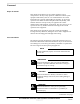
SC 4812ET – SC 614/SC 614T Companion Frame Installation – continued Table E-2: Removing the Duplexers (RX2, RX4 and RX6) from the SC 614 n Step Action 6 After removing the three (3) diversity duplexers (RX2, RX4 and RX6), slide the top and bottom brackets back to their original positions and torque the six (6) M6 nuts to 5 N–m (45 in–lbs) 7 Install six Type N bulkhead connectors to the Main Ground Bar (MGB) in the holes for RX 2 IN, RX 2 IN, RX 2 IN, RX 1 OUT, RX 1 OUT, and RX 1 OUT (see Figure E-5).
SC 4812ET – SC 614/SC 614T Companion Frame Installation – continued Figure E-4: Duplexer/Directional Coupler TOP MOUNTING BRACKET TX RX FWD RFL DDC BOTTOM MOUNTING BRACKET Figure E-5: Cut–a–way view of SC 614 (from the top looking down on Duplexers) E SC 614 WITH DUPLEXERS REMOVED INTERCONNECT AT THE MAIN GROUND BAR RX 1 OUT RX 2 IN RX 1 OUT RX 1 OUT RX 2 IN RX 2 IN RXDC (R1) ERXDC (R2) . . .
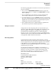
SC 4812ET – SC 614/SC 614T Companion Frame Installation – continued Removing the Diversity RXDC (R2) The procedure to physically remove the diversity RXDC from the SC 614 cabinet is described in Table E-3. Table E-3: Removing the Diversity RXDC from the SC 614 n Step Action 1 Unplug the ganged connectors PL1 and PL2 from the Diversity RXDC (R2) in the BTS. (See Figure E-6 and Figure E-7). 2 Disconnect the 8–pin and 14–pin connectors, P2 and P1, respectively.
SC 4812ET – SC 614/SC 614T Companion Frame Installation – continued Figure E-7: Location of RXDCs and ERXDCs T–15 TORX SCREWS R1 R2 E Installing an ERXDC in the SC 614 The procedure to physically install an RXDC in the SC 614 cabinet is described in Table E-4. . . . continued on next page 164 SCTM 4812ET RF and Power Cabinet Hardware Installation Manual DRAFT Apr 2001 V0E.
SC 4812ET – SC 614/SC 614T Companion Frame Installation – continued Table E-4: Installing an ERXDC in the SC 614 Cabinet n Step Action 1 In the R2 location, slide the bracket up and install the ERXDC with the three SMA connectors along the bottom edge facing forward. Slide the bracket down over the ERXDC. Using a T15 TORX screw driver, torque the two (2) pan head screws to 2 N–m (16 in–lbs). 2 Connect the SMA plug to the SMA jacks (J1, J2, and J3) on the ERXDC (see Figure E-6).
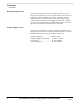
SC 4812ET – SC 614/SC 614T Companion Frame Installation – continued Cabling the SC 4812ET to the SC 614 The procedure to physically cable the RXDC in the SC 614 is described in Table E-5. Table E-5: Connecting SC 4812ET to SC 614 n Step E 166 Action 1 Unplug the ganged connectors PL1 and PL2 from the RXDC (R1). 2 Disconnect the SMB plugs from the J1300A port (main RX) and J1300B port (diversity RX) on each TRX. Snip off the tie wrap that hold the cable together.
SC 4812ET – SC 614/SC 614T Companion Frame Installation – continued Figure E-8: Connecting SC 4812ET to SC 614 9186180H01 0983599H01 TX3 RX5 TX2 RX3 TX1 RX1 SC 614T DDC’s SC 614 E 3009923W04 (9) 1A EXTERNAL CABLES 1B IN PORTS OUT PORTS 2A 2B 3A SC 614 BULKHEAD 3B TX3 RX3 SC 4812ET EXPANSION PORTS 20 Pair RGD Punchblock Board (RGPS) 1A TX2 RX2 4A TX1 RX1 2A 5A 3A 6A 1B 2B 4B 5B 6B (Alarms/ Spans) RF Expansion Ports 1A 2A 3A 1B 2B RGD/RGPS 50 Pair Punch Block 3B Micro– wave P
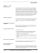
SC 4812ET – SC 614/SC 614T Companion Frame Installation – continued Figure E-9: Cabling of SC 4812ET to SC 614 BTS ÌÌÌÌÌÌÌÌÌÌÌÌÌÌ ÌÌÌÌÌÌÌÌÌÌÌÌÌÌ ÌÌÌÌÌÌÌÌÌÌÌÌÌÌ ÌÌÌÌÌÌÌÌÌÌÌÌÌÌ ÌÌÌÌÌÌÌÌÌÌÌÌÌÌ ÌÌÌÌÌÌÌÌÌÌÌÌÌÌ ÌÌÌÌÌÌÌÌÌÌÌÌÌÌ ÌÌÌÌÌÌÌÌÌÌÌÌÌÌ ÌÌÌÌÌÌÌÌÌÌÌÌÌÌ ÓÓ ÑÑ Ó Ñ ÌÌÌÌÌÌÌÌÌÌÌÌÌÌ ÓÓ ÑÑ Ó Ñ ÌÌÌÌÌÌÌÌÌÌÌÌÌÌ ÌÌÌÌÌÌÌÌÌÌÌÌÌÌ ÌÌÌÌÌÌÌÌÌÌÌÌÌÌ Ó Ñ ÌÌÌÌÌÌÌÌÌÌÌÌÌÌ Ó Ñ ÌÌÌÌÌÌÌÌÌÌÌÌÌÌ ÌÌÌÌÌÌÌÌÌÌÌÌÌÌ ÌÌÌÌÌÌÌÌÌÌÌÌÌÌ RX Ant–1A C1 TX1 C2 C3 C4 RX1A RX Ant–2A C1 TX2 C2 C3 C4 RX2A RX C1 TX3 Ant–3A C2 C3 C4 RX
Appendix F: SC 4812ET to SC 4812ET DC Power Sharing and Frame Installation This section includes... Scope and Introduction . . . . . . . . . . . . . . . . . . . . . . . . . . . . . . . . Configuration . . . . . . . . . . . . . . . . . . . . . . . . . . . . . . . . . . . . . . . 169 170 DC Power Interconnect to RF Cabinet . . . . . . . . . . . . . . . . . . . . 171 Cabling SC 4812ET RF Cabinet to SC 4812ET RF Cabinet . . . 175 Applying AC Power . . . . . . . . . . . . . . . . . . . . . . . . . . . . .
SC 4812ET to SC 4812ET DC Power Sharing and Frame Installation – continued Configuration The SC 4812ET Power Cabinet consists of a rectifier system with up to six (6) 27 Volt DC, 70 Amp modules, depending on the number of carriers it is required to support in the SC 4812ET RF Cabinet. Connections to the SC 4812ET are made via six (6) #2/0 AWG superflex (three red and three black) cables, to allow redundancy on the DC connections, and to minimize voltage drop.
SC 4812ET to SC 4812ET DC Power Sharing and Frame Installation – continued IMPORTANT * Due to the reduction in load capacity of the power cabinet, the battery/rectifier configuration and number of sector–carriers that can be supported in the SC 4812ET RF Cabinet are changed compared to the standard SC 4812ET documentation. Table G-1 details the recommended configurations when co–locating two 4812ET RF Cabinets.
SC 4812ET to SC 4812ET DC Power Sharing and Frame Installation – continued Table F-2: Wire, Lug, and Die Table Wire Size Motorola Part Number for Lugs AWG CGDS256306951514 Color and Die Code Metric (mm) Welding (Superflex) Circular Mills Area 2/0 AWG 60–70 1/0 133,400 BLACK 45 CGDS256306951539 3/0 AWG 85–95 2/0 167,800 ORANGE 50 CGDS256306951515 4/0 AWG 100–107 3/0 211,600 PURPLE 54 CGDS256306951540 N/A N/A 4/0 250,000 YELLOW 62 Power input connections Figure F-2 shows how the
SC 4812ET to SC 4812ET DC Power Sharing and Frame Installation – continued Installation Procedure WARNING Do NOT wear a wrist strap when servicing the power supplies or power distribution cabling. Serious personal injury can result. CAUTION Before starting the procedure, ensure that the Power Cabinet main DC breakers are turned ”OFF”. Follow the procedure in Table F-3 to install the DC power cables (refer to Figure F-1, Figure F-2 and Figure 5-1).
SC 4812ET to SC 4812ET DC Power Sharing and Frame Installation – continued Table F-3: Procedure to Install DC Power Cables Step Action 8 Insert the cable into the barrel of the right angle crimp lug. 9 Crimp the lug to the cable. 10 Repeat steps 8–9 for the remaining power cable(s). NOTE Be sure to observe the polarity of each cable as you install the cables to the power input studs on the RF Cabinet.
SC 4812ET to SC 4812ET DC Power Sharing and Frame Installation – continued Cabling SC 4812ET RF Cabinet to SC 4812ET RF Cabinet The objective of this procedure is to interconnect the cables between two SC 4812ET RF cabinets. CAUTION Before starting the procedure, ensure that the Power Cabinet main DC breakers are turned “OFF”. Tools and equipment required: Refer to Chapter 5 “Cabinet Cabling” for the tools requirement to interconnect the cables between two RF cabinets.
SC 4812ET to SC 4812ET DC Power Sharing and Frame Installation – continued Notes F 176 SCTM 4812ET RF and Power Cabinet Hardware Installation Manual DRAFT Apr 2001 V0F.
Appendix G: SC 4812ET – SC 4812ET Companion Frame Installation This section includes... Scope and Introduction . . . . . . . . . . . . . . . . . . . . . . . . . . . . . . . . Tools Needed . . . . . . . . . . . . . . . . . . . . . . . . . . . . . . . . . . . . . . . Required documents . . . . . . . . . . . . . . . . . . . . . . . . . . . . . . . . . . Installing an EMPC in a SC 4812ET RF Starter Frame . . . . . . .
SC 4812ET – SC 4812ET Companion Frame Installation – continued Installing an EMPC in a SC 4812ET RF Starter Frame Table G-1 descripts the procedure for installing an EMPC card needed when connecting a SC 4812ET expansion frame. Table G-1: Installing an EMPC in the SC 4812ET Starter Frame Step Action 1 Locate the MPC–B card in the SC 4812ET RF starter frame to be removed. 2 Disconnect coaxial cables connecting to the MPC using a 5/16” wrench.
SC 4812ET – SC 4812ET Companion Frame Installation – continued Figure G-1: RX Expansion Cabling of SC 4812ET to SC 4812ET BTS ÌÌÌÌÌÌÌÌÌÌÌÌÌÌ ÌÌÌÌÌÌÌÌÌÌÌÌÌÌ ÌÌÌÌÌÌÌÌÌÌÌÌÌÌ ÌÌÌÌÌÌÌÌÌÌÌÌÌÌ ÌÌÌÌÌÌÌÌÌÌÌÌÌÌ ÌÌÌÌÌÌÌÌÌÌÌÌÌÌ ÌÌÌÌÌÌÌÌÌÌÌÌÌÌ ÌÌÌÌÌÌÌÌÌÌÌÌÌÌ ÌÌÌÌÌÌÌÌÌÌÌÌÌÌ ÌÌÌÌÌÌÌÌÌÌÌÌÌÌ Ó Ñ ÌÌÌÌÌÌÌÌÌÌÌÌÌÌ Ó Ñ ÌÌÌÌÌÌÌÌÌÌÌÌÌÌ ÌÌÌÌÌÌÌÌÌÌÌÌÌÌ ÌÌÌÌÌÌÌÌÌÌÌÌÌÌ Ñ Ó ÌÌÌÌÌÌÌÌÌÌÌÌÌÌ Ñ Ó Ñ Ó ÌÌÌÌÌÌÌÌÌÌÌÌÌÌ ÌÌÌÌÌÌÌÌÌÌÌÌÌÌ ÌÌÌÌÌÌÌÌÌÌÌÌÌÌ ÌÌÌÌÌÌÌÌÌÌÌÌÌÌ ÌÌÌÌÌÌÌÌÌÌÌÌÌÌ ÌÌÌÌÌÌÌÌÌÌÌÌÌÌ ÌÌÌÌÌÌÌÌÌÌÌÌÌÌ ÌÌÌÌÌÌÌÌÌÌÌÌÌÌ ÌÌÌÌÌÌÌÌÌÌÌÌÌÌ ÌÌÌÌ
SC 4812ET – SC 4812ET Companion Frame Installation – continued Notes G 180 SCTM 4812ET RF and Power Cabinet Hardware Installation Manual DRAFT Apr 2001 V0G.
Appendix H: Installing RF GPS This section includes... Introduction . . . . . . . . . . . . . . . . . . . . . . . . . . . . . . . . . . . . . . . . . Installation Procedure . . . . . . . . . . . . . . . . . . . . . . . . . . . . . . . . . RF GPS Mounting Considerations . . . . . . . . . . . . . . . . . . . . . . . 181 182 184 Tables Table H-1: Installing the RF GPS . . . . . . . . . . . . . . . . . . . . . . . . Table H-2: Mounting Considerations . . . . . . . . . . . . . . . . . . . . .
Installing RF GPS – continued Installation Procedure Table H-1 lists the step of installing the RF GPS system. Table H-1: Installing the RF GPS Step Action 1 Determine the mounting location (see RF GPS Mounting Considerations in this chapter). 2 Install the mounting kit at the RF GPS location of choice. Use the appropriate mounting bolts for mounting surface.
Installing RF GPS – continued Figure H-1: GPS Installation and Parts 4” NOTE: 1. TOTAL WEIGHT FOR GPS ANTENNA ASSEMBLY – 0.65 LBS.
Installing RF GPS – continued RF GPS Mounting Considerations The RF GPS Head requires specific mounting considerations in order to properly observe the GPS satellites. Table H-2: Mounting Considerations n Consideration 1 The mounting pipe for the RF GSP Head should be mounted vertically with less than five (5) degrees of tilt. 2 The RF GPS Head requires a clear view of the sky, preferably to within ten (10) degrees of the horizon in all directions.
Appendix I: Minimum CSU Requirements for SC 4812ET BTS This section includes... CSU Requirements . . . . . . . . . . . . . . . . . . . . . . . . . . . . . . . . . . . 185 Tables Table G-1: Network Interface (8–pin RJ48C Connector) . . . . . . Table I-2: Terminal Interface (8–pin RJ48C Connector) . . . . . . Table I-2: Power Connector . . . . . . . . . . . . . . . . . . . . . . . . . . . .
Minimum CSU Requirements for SC 4812ET BTS – continued T1 Span Requirements: – – – – Nominal Line Rate: 1.544 Mbps Line Impedance: 100 Ohms Line Code: AMI or B8ZS Framing Format: SF or ESF per ANSI T1.403, ITU–T G.704 Terminal Interface: – Shorthaul: ANSI T1.102, ITU–T G.703 – Input: DSX–1 to –10 dB – Output: DSX–1 with equalization up to 655 feet. Network Interface: – Longhaul: ANSI T1.403, ITU–T G.703 – Input: DSX–1 to –27.5 dB – Output: Per ANSI T1.403 with line build–out to 15 dB.
Minimum CSU Requirements for SC 4812ET BTS – continued Network Interface: – Line Impedance: 120 Ohms (75 Ohms may require external adapter) – Compliance: Per ITU–T G.703 Regulatory – International: Safety: For a CSU external to the SC 4812ET, the requirement is to be an certified CSU, with testing performance by a National Certification Body (NCB) participating in the CB scheme under IEC60950. Additional compliance requirements unique to E1 are not know at this time.
Minimum CSU Requirements for SC 4812ET BTS – continued Table I-3: Power Connector Pin# Circuit Name 1 +V 2 Ground 3 –V I 188 SCTM 4812ET RF and Power Cabinet Hardware Installation Manual DRAFT Apr 2001 V0I.
Index Numbers 110 style punch block, 81, 96 Battery Mounting, 65 Battery strings, 33 battery strings, 68 208–265 VAC, 36 Battery Strings Required – Minimun, 33 208/240 VAC power cables, 102 BBX–1, 24 breaker size, 103 A BTS Cabinet, 24 A/C load center/breaker panel, 102 AC Current Requirements, 105 AC Load Center, 103 BTS Cable Descriptions and Part Numbers, 78 BTS transmit and receive path cabling , 93 building codes, 41 AC Power Cabling, 73 C AC Power connection, 36 AC power pedestal, 30, 31,
Index – continued Concrete Mounting – Existing Pad, 61 concrete pad, 42 Concrete Pad and Ground System Installation, 42 Concrete pad and ground system installation, 43 External alarm connector characteristics and requirements, 85 External FRUs, 20 eye–bolts, 62 Conduit Stub Height Detail, 44 F conduit/cable entrance layout, 41 connect the DC battery backup, 99, 140, 159 flush, 37 Connection Materials, 42 Framing Materials – Concrete Pad, 42 crates, 54 FRU, 108 CSM, 23 Customer I/O, 23 G GLI2, 2
Index – continued Installation Hardware, 16 MPC, 23 Installing Batteries, 59 Installing Batteries in the Power Cabinet, 68 N Installing the Remote GPS Hardware, 13 New Concrete Pad Preparation, 41 insulated, 31 New Concrete Pad Mounting, 64 inter-cabinet ca, 74 Intercabinet I/O, 76 O Internal FRU, 25 Internal FRUs, 22 Optimization, 107 Optimize the System, 110 K Outdoor Location Preparation, 34 Knife or Scissors, 51 P L packed, 53 Pad Forms and Conduit Layout, 45, 46, 119 LFR Cable (if ap
Index – continued Report any damage, 58 Static sensitive equipment, 58, 75 Required documents, 13, 14, 17, 18 submersion, 31, 34, 40 RF Cabinet Alarm Cable Connection, 36 surges, 103, 131 RF Cabinet Span and Modem Cable Connection, 36 RF GPS Cable, 36 T RF I/O area, 94 RF I/O Plate, 93 Telco Interface Board TIB, 26 RF interference, 49 Tin Snips, 51 RGPS Cable, 36 Tools and equipment required, 99, 140, 159 RGPS Head, 48 Transmission Lines – RF, 35 RGPS Mounting Considerations, 48 Transmit/