
Installation Instructions
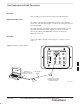

Test Equipment and LMF Connection – continued
PRELIMINARY
SCt300 BTS Hardware Installation, ATP and FRU Procedures
DEC 2000
7-8
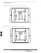
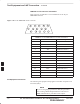
MMI/LMF serial connector information
Refer to Figure 7-8 and Table 7-2 for information for the 15–pin
MMI/LMF connector.
Figure 7-8: 15–Pin MMI/LMF Serial Connector
11 12 13 14 15
678910
12345
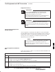
Table 7-2: 15–Pin MMI/LMF Serial Cable Information
Pin# Abbreviation Description
1 RTS Request to Send
2 TXD Transmit Data
3 RXD Receive Data
4 TX+ Ethernet Transmit +
5 TX– Ethernet Transmit –
6 CTS Clear to Send
7 CTS Clear to Send
8 CTS Clear to Send
9 – Open
10 RI Ring Indicator
11 RI Ring Indicator
12 RX+ Ethernet Receive +
13 CTS Clear to Send
14 GND Ground
15 RX– Ethernet Receive –
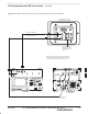
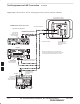
Test Equipment Connection
The following test equipment setup applies to the BTS Acceptance Test
Procedure (ATP).
If you are not going to perform the ATP, then proceed to
the “Creating a Named HyperTerminal Connection for
MMI Communication” procedure in this chapter.
NOTE
7