
Installation Instructions

Full Unit Replacement Procedures – continued
PRELIMINARY
SCt300 BTS Hardware Installation, ATP and FRU Procedures
DEC 2000
9-22
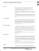
Table 9-14: Remove the Failed Unit
Step Action
3 If DC power is being supplied to the unit or if battery backup is present, open (pull) the DC power
breaker. The white collar on the breaker is visible when the breaker is opened.
4 If AC power is being supplied to the unit, open (pull) the AC power breaker. The white collar on
the breaker is visible when the breaker is opened.
5 Turn the power off at the main power source (AC and/or DC).
6 Use a T30 TORX tamper bit to remove the two tamper–resistant screws that hold the Site I/O
junction box (or environmental cover) to the BTS. Refer to Figure 9-4 in the “Site I/O Junction
Box Replacement” procedure.
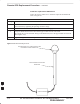
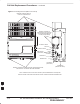
7 Disconnect the AC input cable from the unit. Refer to Figure 9-7.
8 Disconnect the DC input cable from the unit. Refer to Figure 9-7.
9 Disconnect the antenna cable(s) from the unit. Refer to Figure 9-7.
10 Disconnect the MIB cables from the unit (if equipped). Refer to Figure 9-7.
11 Disconnect the SU cables from the unit (if equipped). Refer to Figure 9-7.
12 Remove the two mounting screws that hold the short duration battery (if present) to the unit.
Refer to NO TAG in the “Short Duration Battery Replacement Procedures” procedure and
Figure 9-7.
13 Attach the installation handles to the unit. Refer to the “Attaching Installation Handles to the
Unit” procedure in Chapter 6.
14 Use a T30 Tamper bit to remove the two screws that hold the unit to the mounting bracket.
15 Remove the pin or lock (if equipped) from the unit.
16 Remove the unit from the mounting bracket.
9