
Installation Instructions

Test Equipment Setup – continued
DEC 2000
7-35
SCt300 BTS Hardware Installation, ATP and FRU Procedures
PRELIMINARY
Power Meter GPIB Setup
Precise transmit output power measurements are made using a
broadband power meter with a sensitive power sensor. Follow the steps
outlined in Table 7-20 to set the GPIB address of the power meter.
Refer to Figure 7-13.
Table 7-20: Gigatronics Power Meter GPIB Address Procedure
Step Action
! CAUTION
Do not connect/disconnect the power meter sensor cable with ac power applied to the meter.
Disconnection could result in destruction of the sensing element or mis–calibration.
1 Make sure the power meter POWER pushbutton is OFF. Connect the power sensor cable to the
SENSOR input. Set the POWER pushbutton to ON.
NOTE
N
O
TE
The calibration should be performed only after the power meter and sensor have been allowed to
warm–up and stabilize for a minimum of 60 minutes.
2 Verify that the Power Meter GPIB mode and address are set correctly:
S Power Meter (currently used by LMF for calibration)
GPIB address = 13 Consult test equipment OEM documentation for additional info as required).
– Press MENU. Use the b arrow key to select CONFIG MENU and press ENTER.
– Use the b arrow key to select GPIB and press ENTER.
– Use the by arrow keys as required to set MODE to 8541C or 8542C (as appropriate).
– Press ' and use the by arrow keys as required to set ADDRESS to 13.
– Press ENTER.
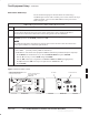
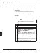
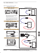
Figure 7-13: Power Meter Detail
CONNECT POWER SENSOR
WITH POWER METER
TURNED OFF
CONNECT POWER SENSOR TO
CALIBRATOR POWER REFERENCE WHEN
CALIBRATING/ZEROING UNIT
FRONT View REAR View
GPIB CONNECTION
AC POWER
7