Chapter 6: Installing the Unit and Installation Check Off List Table of Contents DEC 2000 Unit Installation Overview . . . . . . . . . . . . . . . . . . . . . . . . . . . . . . . . . . . . . . . . . Overview . . . . . . . . . . . . . . . . . . . . . . . . . . . . . . . . . . . . . . . . . . . . . . . . Unit Installation Procedure Order . . . . . . . . . . . . . . . . . . . . . . . . . . . . . 6-1 6-1 6-1 Connector Locations . . . . . . . . . . . . . . . . . . . . . . . . . . . . . . . . . . . . . . . .
Table of Contents 6 – continued Attaching the Short Duration Battery to the Unit (optional) . . . . . . . . . . . . . . . Objective . . . . . . . . . . . . . . . . . . . . . . . . . . . . . . . . . . . . . . . . . . . . . . . . Required Tools and Materials . . . . . . . . . . . . . . . . . . . . . . . . . . . . . . . . Procedure to Attach the Battery to the Unit . . . . . . . . . . . . . . . . . . . . . 6-17 6-17 6-17 6-17 Short Duration Battery Cabling . . . . . . . . . . . . . . . . . . . . . . . . .
Table of Contents – continued Powering on Unit and Mounting the Solar Cover . . . . . . . . . . . . . . . . . . . . . . . Objective . . . . . . . . . . . . . . . . . . . . . . . . . . . . . . . . . . . . . . . . . . . . . . . . You May Want to Wait . . . . . . . . . . . . . . . . . . . . . . . . . . . . . . . . . . . . . . Tools Required . . . . . . . . . . . . . . . . . . . . . . . . . . . . . . . . . . . . . . . . . . . . Procedure to Power On Unit and Mount Solar Cover . . . . . . . . . . . . . .
Table of Contents – continued Notes 6 SCt300 BTS Hardware Installation, ATP and FRU Procedures PRELIMINARY DEC 2000
Unit Installation Overview Overview This chapter provides the procedures for unit installation and cabling. The site cabling has been installed and routed to the location of the BTS. In this chapter, the cables will be attached to the unit(s). Cabling installation will be repeated as necessary for each unit at the BTS.
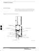
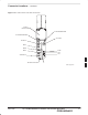
Connector Locations Connector Locations Figure 6-1, Figure 6-2, and Figure 6-3 show the location of the cable connectors on the Microcell, Picocell, and Primary Surge Suppressor. The system configuration determines which connectors are used. Figure 6-1: Location of MicroCell Unit Connectors SITE I/O JUNCTION BOX 6 AC POWER BREAKER DC POWER BREAKER DC INPUT AC INPUT MIB C MIB B MIB A SU RF SU 2 SU 1 ANTENNA A ANTENNA B TIE WRAP LOCATION 6-2 0169–O_IL.
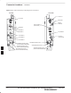
Connector Locations – continued Figure 6-2: Location of PicoCell Unit Connectors SITE I/O JUNCTION BOX AC POWER BREAKER DC POWER BREAKER AC INPUT DC INPUT MIB C MIB B MIB A SU RF SU 2 SU 1 ANTENNA A 6 TIE WRAP LOCATION 0170–O_IL.
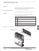
Connector Locations – continued Figure 6-3: Location of Primary Surge Suppressor Connectors LEFT SIDE RIGHT SIDE SITE I/O 1 SITE I/O 2 GROUND 1 EARTH GROUND SITE I/O INPUT (Conduit Hole) GROUND 4 GROUND 3 GROUND 2 AC POWER 1 AC POWER 2 AC INPUT (Conduit Hole) AC POWER 3 AC POWER 4 ANTENNA PROTECTOR 1 ANTENNA PROTECTOR 6 (FOR FUTURE EXPANSION) ANTENNA PROTECTOR 5 (FOR FUTURE EXPANSION) ANTENNA PROTECTOR 4 (FOR FUTURE EXPANSION) 6 6-4 ANTENNA PROTECTOR 2 ANTENNA PROTECTOR 3 (FOR FUTURE EXPANSION) S
Attaching Back Fin Cover to Unit Objective The objective of this procedure is to attach the back fin cover to the PicoCell and MicroCell units. The front fin cover is mounted to the unit after the unit is mounted to the mounting bracket. When to Use the Fin Covers The fin covers should always be used in an indoor application. Procedure Attach the rear fin cover to the unit by following the procedures in Table 6-1 and the information in Figure 6-4.
Attaching Optional Installation Handles to the Unit Objective The objective of this procedure is to attach the optional installation handles to the unit. The location for the handles is shown in Figure 6-5. The handles should be used when lifting or carrying the unit. Required Tools and Materials Tools Attaching the installation handles to the unit requires: S T30 Torx tamper bit S Torque driver wrench, 1/4–in.
Attaching Installation Handles to the Unit – continued Figure 6-5: Attaching the Installation Handles to the Unit (Picocell Shown) HOLES USED FOR MOUNTING HANDLES HOLES USED FOR MOUNTING HANDLES LEFT HANDLE 6 RIGHT HANDLE M6X19 (4) 0164–O_IL.
Attaching Unit to Mounting Bracket Objective The objective of this procedure is to attach the unit to the mounting bracket. This procedure applies to mounting brackets that are attached to a rack, wall, ceiling or pole. This procedure also applies to both the MicroCell and PicoCell units. Background The unit attaches to the mounting bracket with two (2) M6 screws and the provided pin or a customer–supplied padlock. WARNING For ceiling mount applications, two people must do this procedure.
Attaching Unit to Mounting Bracket – continued Procedure to Attach the Unit to the Mounting Bracket Follow the procedure in Table 6-4 to attach the unit to the mounting bracket. Refer to Figure 6-6. WARNING For ceiling mount applications, two people must do this procedure. One person must steady the unit while the second person installs the unit. CAUTION Use caution when resting the MicroCell or PicoCell unit on the hooks of the mounting bracket. Do not leave unit supported by hooks only.
Attaching Unit to Mounting Bracket – continued Figure 6-6: Attaching the Unit to the Mounting Bracket MOUNTING BRACKET HOOKS M6 SCREWS (2) SLIDE PIN THROUGH HOLES IN BRACKET AND SCREW TOGETHER 6 ATTACH THE HANDLES TO THE UNIT BEFORE LIFTING MOUNTING BRACKET PIN (P/N 5587660C03) 6-10 SCt300 BTS Hardware Installation, ATP and FRU Procedures PRELIMINARY DEC 2000
Earth Ground Cabling Objective The objective of this procedure is to attach the earth ground cabling to one or more MicroCell or PicoCell units. This procedure covers just the grounding cables that attach to the MicroCell or PicoCell. Other Grounding Considerations Grounding considerations beyond the ground cables that attach to the MicroCell and PicoCell are summarized in Appendix A. Refer to Appendix A and the site documentation for other grounding considerations.
Earth Ground Cabling – continued Table 6-6: Procedure to Attach the Earth Ground Cables Step Action 3 Replace one lock washer and nut on the ground stud and tighten to 5 N–m. 4 Attach the ground cable from the Site I/O junction box (cable B) to the ground stud on the mounting bracket. 5 Replace the second lockwasher and hex nut to the ground stud on mounting bracket. Use a torque wrench and a 13mm socket to tighten to 5.0 N–m.
Earth Ground Cabling – continued Figure 6-8: Grounding Stud on Mounting Bracket MOUNTING BRACKET LOCK WASHER NUT LOCK WASHER NUT GROUNDING STUD CUSTOMER UNIT SITE I/O GROUND LUG GROUND LUG 6 DEC 2000 SCt300 BTS Hardware Installation, ATP and FRU Procedures PRELIMINARY 6-13
Attaching Front Fin Cover to Unit Objective The objective of this procedure is to attach the front fin cover to the PicoCell and MicroCell units. When to Use the Fin Covers Always use fin covers for an indoor application. Procedure Follow the procedure in Table 6-7 to attach the front fin cover to the unit. Refer to Figure 6-9. Table 6-7: Procedure to Attach Front Fin Cover to Unit Step Action 1 Center fin cover on the fins of the unit. See Figure 6-9 for snap locations.
Attaching the Site I/O Junction Box to the Unit Objective The objective of this procedure is to attach the Site I/O junction box to the unit. The location for the Site I/O junction box is shown in Figure 6-10. If you do not mount a Site I/O Junction box to a unit, leave the installed Site I/O caps on the Site I/O Junction box connectors. Required Tools and Materials The following tools and materials are necessary to do this procedure: S Torque driver wrench, 1/4–in.
Attaching the Site I/O Junction Box to the Unit – continued Figure 6-10: Attaching the Site I/O Junction Box to the Unit SITE I/O JUNCTION BOX CAPTIVE SCREWS 6 Procedure to Attach a Site I/O Cap to the Unit (optional) Use the following procedure in Table 6-9 to attach a Site I/O Cap to the unit. Table 6-9: Procedure to Attach a Site I/O Cap to the Unit (optional) Step 6-16 Action 1 Position the Site I/O cap, Motorola Part Number 3888121C01, over the Site I/O socket.
Attaching the Short Duration Battery to the Unit (optional) Objective The objective of this procedure is to attach the short duration battery to the unit. Required Tools and Materials Attaching the battery to the unit requires: S T30 Torx tamper bit, 1/4–in. hex S Torque driver wrench, 1/4–in. hex female drive, 0–10 N–M S Two (2) Screws M6x19 (Motorola Part Number 0387541C03) Procedure to Attach the Battery to the Unit Follow the procedure in Table 6-10 to attach the short duration battery to the unit.
Attaching the Short Duration Battery to the Unit (optional) – continued Figure 6-11: Attaching the Short Duration Battery to the Unit M6X19 SCREWS (2) CONNECT TO DC INPUT CONNECTOR WHEN BATTERY HAS BEEN SECURED 6 SHORT DURATION BATTERY 6-18 SCt300 BTS Hardware Installation, ATP and FRU Procedures PRELIMINARY DEC 2000
Short Duration Battery Cabling Objective The objective of this procedure is to attach the short duration battery cable. Battery Cable The battery cable is part of the battery assembly. The same type connector is used for the short duration battery and DC input cables. Procedure Use the following procedure in Table 6-11 to attach the short duration battery (DC input) cable to the DC input connector. Refer to Figure 6-12. The cable should be connected before the solar cover is attached.
Short Duration Battery Cabling – continued Figure 6-12: Battery Cable Installation DC INPUT CONNECTOR BATTERY CABLE IS PART OF BATTERY ASSEMBLY 6 6-20 SCt300 BTS Hardware Installation, ATP and FRU Procedures PRELIMINARY DEC 2000
AC Power Cabling Objective The objective of this procedure is to attach the AC input power cable to the unit. Use this procedure only when AC power is used to power the unit. If the Primary Surge Suppressor is not used, the AC Installation Box is required for all outdoor mounting applications. WARNING This equipment uses dangerous voltages and is capable of causing death. Use extreme caution when handling and testing this equipment.
AC Power Cabling – continued Figure 6-13: AC Power Cabling Details AC POWER BREAKER AC INPUT CONNECTOR AC CONDUIT S AC INSTALL BOX OR AC POWER SOURCE OR OPTIONAL PRIMARY SURGE SUPPRESSOR 6 6-22 SCt300 BTS Hardware Installation, ATP and FRU Procedures PRELIMINARY DEC 2000
DC Power Cabling Objective The objective of this procedure is to attach the DC input cable to the unit. Use this procedure only when DC power is used to power the unit. WARNING This equipment uses dangerous voltages and is capable of causing death. Use extreme caution when handling and testing this equipment. Cable Decription The following cables in Table 6-14 are necessary to do this procedure. Table 6-14: DC Input Cable Description and Part Number Cable Qty.
DC Power Cabling – continued Figure 6-14: DC Power Cabling Details DC POWER BREAKER DC INPUT CONNECTOR DC POWER SOURCE U 0178–O_IL.
Antenna Cabling for Sites Equipped With Customer–Supplied Site I/O Interface Objective The objective of this procedure is to attach the antenna cabling for one or more units. If your BTS is equipped with the optional Primary Surge Suppressor, then proceed to the “Antenna Cabling for Sites Equipped with the Optional Primary Surge Suppressor” procedure in Chapter 6. Cable Labels The cable designations are referenced to Table 6-16 in the “Cable Description” area of Chapter 4.
Antenna Cabling for Sites Equipped With Customer–Supplied Site I/O Interface – continued Figure 6-15: Antenna Cabling Details for MicroCell and PicoCell Unit MICROCELL UNIT PICOCELL UNIT ANTENNA B ANTENNA A ANTENNA A 6 C LIGHTNING ARRESTOR C RX ANTENNA 6-26 C LIGHTNING ARRESTOR C TX/RX ANTENNA C LIGHTNING ARRESTOR C TX/RX ANTENNA SCt300 BTS Hardware Installation, ATP and FRU Procedures PRELIMINARY DEC 2000
Antenna Cabling for Sites Equipped With Customer–Supplied Site I/O Interface – continued Figure 6-16: Antenna Cabling for Two Microcells MICROCELL UNIT MICROCELL 1 ANT A RFT ANT B LA ANTENNA 1 TX/RX LA ANTENNA 2 TX/RX C MICROCELL 2 ANTENNA A ANT A RFT ANTENNA B KEY ANT B C LA = LIGHTNING ARRESTOR RFT = 50 OHM RF TERMINATOR Figure 6-17: Antenna Cabling for Three Microcells 6 MICROCELL UNIT MICROCELL 3 MICROCELL 1 ANT A ANT A RFT ANT B ANT B LA ANTENNA 1 TX/RX LA ANTENNA 3 TX/RX LA AN
Antenna Cabling for Sites Equipped With Customer–Supplied Site I/O Interface – continued Figure 6-18: Antenna Cabling for Four Microcells MICROCELL UNIT MICROCELL 3 MICROCELL 1 ANT A RFT ANT A RFT ANT B ANT B LA ANTENNA 1 TX/RX LA ANTENNA 3 TX/RX LA ANTENNA 2 TX/RX LA ANTENNA 4 TX/RX C C MICROCELL 4 MICROCELL 2 ANTENNA A ANTENNA B KEY ANT A RFT ANT A RFT ANT B ANT B C LA = LIGHTNING ARRESTOR C RFT = 50 OHM RF TERMINATOR 6 Figure 6-19: Antenna Cabling for Two Picocells PICOCELL UNIT
Antenna Cabling for Sites Equipped With Customer–Supplied Site I/O Interface – continued Figure 6-20: Antenna Cabling for Three Picocells PICOCELL UNIT PICOCELL 3 PICOCELL 1 ANT A ANT A C LA ANTENNA 1 TX/RX LA ANTENNA 3 TX/RX LA ANTENNA 2 TX/RX C PICOCELL 2 ANTENNA A ANT A KEY C LA = LIGHTNING ARRESTOR Figure 6-21: Antenna Cabling for Four Picocells PICOCELL UNIT 6 PICOCELL 3 PICOCELL 1 ANT A ANT A C LA ANTENNA 1 TX/RX LA ANTENNA 3 TX/RX LA ANTENNA 2 TX/RX LA ANTENNA 4 TX/R
Antenna Cabling for Sites Equipped with Optional Primary Surge Suppressor Objective The objective of this procedure is to attach the antenna cabling for one or more units at a site equipped with the optional Primary Surge Suppressor. Cable Labels The cable designations are referenced to Table 6-17 in the “Cable Description” area of Chapter 4. Cable Descriptions The following cables in Table 6-17 are necessary to do this procedure. Table 6-17: Cable Descriptions and Part Numbers Cable Qty.
Antenna Cabling for Sites Equipped with Optional Primary Surge Suppressor – continued Figure 6-22: Installation of Third and Fourth Antenna Lightning Arrestors 3/4–IN NUT LOCKWASHER ANTENNA LIGHTNING ARRESTORS 6 DEC 2000 SCt300 BTS Hardware Installation, ATP and FRU Procedures PRELIMINARY 6-31
Antenna Cabling for Sites Equipped with Optional Primary Surge Suppressor – continued Figure 6-23: Antenna Cabling Details for MicroCell and PicoCell Unit Equipped with Primary Surge Suppressor MICROCELL UNIT PICOCELL UNIT ANTENNA A ANTENNA B ANTENNA A D D PRIMARY SURGE SUPPRESSOR 2 6 C PRIMARY SURGE SUPPRESSOR 1 D C 1 C TX/RX ANTENNA RX ANTENNA TX/RX ANTENNA PRIMARY SURGE SUPPRESSOR (LEFT SIDE) PRIMARY SURGE SUPPRESSOR (RIGHT SIDE) ANTENNA LIGHTNING ARRESTOR 1 ANTENNA LIGHTNING ARRESTOR 2 6-
Antenna Cabling for Sites Equipped with Optional Primary Surge Suppressor – continued Figure 6-24: Antenna Cabling for Two Microcells Equipped with Primary Surge Suppressor PRIMARY SURGE SUPPRESSOR (RIGHT SIDE) MICROCELL UNIT MICROCELL 1 ANT A RFT ANT B D 1 2 PRIMARY SURGE SUPPRESSOR MICROCELL 2 C ANTENNA 1 TX/RX C ANTENNA 2 TX/RX ANTENNA PROTECTOR 1 ANTENNA B ANTENNA A ANTENNA PROTECTOR 2 ANT A RFT ANT B D RFT KEY = 50 OHM RF TERMINATOR 6 DEC 2000 SCt300 BTS Hardware Installation, ATP and F
Antenna Cabling for Sites Equipped with Optional Primary Surge Suppressor – continued Figure 6-25: Antenna Cabling for Three Microcells Equipped with Primary Surge Suppressor MICROCELL 3 ANT A MICROCELL 1 D ANT B D ANT A RFT ANT B D 1 C ANTENNA 1 TX/RX 2 C ANTENNA 2 TX/RX 3 C ANTENNA 3 TX/RX 4 C ANTENNA 4 RX PRIMARY SURGE SUPPRESSOR MICROCELL 2 ANT A RFT ANT B MICROCELL UNIT D PRIMARY SURGE SUPPRESSOR (LEFT SIDE) PRIMARY SURGE SUPPRESSOR (RIGHT SIDE) 6 ANTENNA A ANTENNA B KEY RFT = 50 OHM RF T
Antenna Cabling for Sites Equipped with Optional Primary Surge Suppressor – continued Figure 6-26: Antenna Cabling for Four Microcells Equipped with Primary Surge Suppressor MICROCELL 3 MICROCELL 1 ANT A RFT ANT A RFT ANT B ANT B D 1 C D ANTENNA 1 TX/RX 2 C ANTENNA 2 TX/RX 3 C ANTENNA 3 TX/RX MICROCELL 4 4 C ANTENNA 4 TX/RX PRIMARY SURGE SUPPRESSOR MICROCELL 2 ANT A RFT ANT A RFT ANT B ANT B MICROCELL UNIT D D PRIMARY SURGE SUPPRESSOR (RIGHT SIDE) PRIMARY SURGE SUPPRESSOR (LEFT SIDE) 6
Antenna Cabling for Sites Equipped with Optional Primary Surge Suppressor – continued Figure 6-27: Antenna Cabling for Two Picocells Equipped with Primary Surge Suppressor PICOCELL UNIT PRIMARY SURGE SUPPRESSOR (RIGHT SIDE) PICOCELL 1 ANT A D C 2 C ANTENNA 2 TX/RX PRIMARY SURGE SUPPRESSOR PICOCELL 2 ANTENNA 1 TX/RX 1 ANTENNA PROTECTOR 1 ANTENNA A ANTENNA PROTECTOR 2 ANT A 6 D Figure 6-28: Antenna Cabling for Three Picocells Equipped with Primary Surge Suppressor PICOCELL UNIT PRIMARY SURGE SU
Antenna Cabling for Sites Equipped with Optional Primary Surge Suppressor – continued Figure 6-29: Antenna Cabling for Four Picocells Equipped with Primary Surge Suppressor PICOCELL 3 ANT A PICOCELL 1 1 C ANT A D D ANTENNA 1 TX/RX 2 C ANTENNA 2 TX/RX 3 C ANTENNA 3 TX/RX PICOCELL 4 PICOCELL 2 ANT A ANT A D PICOCELL UNIT 4 C ANTENNA 4 TX/RX PRIMARY SURGE SUPPRESSOR D PRIMARY SURGE SUPPRESSOR (LEFT SIDE) PRIMARY SURGE SUPPRESSOR (RIGHT SIDE) 6 ANTENNA A ANTENNA PROTECTOR 4 (SEE NOTE) NOTE:
MIB Cabling for Multi–Unit Configurations Overview The objective of this procedure is to attach the MIB cabling for a multi–BTS configuration. Cable Labels The cable designations are referenced in Table 4–1 in the “Cable Descriptions” procedure in Chapter 4.
MIB Cabling for Multi–Unit Configurations – continued Table 6-21: Microcell Expansion Kit for Units 1 to 2 Long MIB A (Non–Cubicle) – T448AM Cable Qty. Motorola Part Number Description n/a 2 5882106P01 50 Ohm Antenna Terminator A 1 3087701C02 Ground cable, 8 -AWG, insulated copper wire. Requires one ring lug connector.
MIB Cabling for Multi–Unit Configurations – continued Table 6-25: Microcell/Picocell Expansion Kit for Units 2 to 3 Long 5m MIB B – T448AS Cable Qty. Motorola Part Number Description A 1 3087701C02 Ground cable, 8 -AWG, insulated copper wire. Requires one ring lug connector.
MIB Cabling for Multi–Unit Configurations – continued Table 6-28: Picocell Expansion Kit for Units 3 to 4 Current 2M MIBs B and C – T448AV Cable Qty. Motorola Part Number Description n/a 2 5882106P01 50 Ohm Antenna Terminator A 1 3087701C02 Ground cable, 8 -AWG, insulated copper wire. Requires one ring lug connector.
MIB Cabling for Multi–Unit Configurations – continued Figure 6-30: MIB Cabling for Two Units MICROCELL SHOWN UNIT 1 MIB C MIB B MIB A E/1 MIB (MICROCELL) H/1 MIB (PICOCELL) K/1 MIB (MICROCELL/CUBICLE) L/1 MIB (PICOCELL/CUBICLE) UNIT 2 MIB C MIB C MIB B MIB A MIB B MIB A Figure 6-31: MIB Cabling for Three Units MICROCELL SHOWN UNIT 3 UNIT 1 MIB C MIB C MIB B MIB B MIB A MT MIB A 6 F/1 MIB (MICRO/PICO) I/1 MIB (MICRO/PICO) UNIT 2 MIB C MIB C MIB B MIB A KEY MT = MIB TERMINATOR 6-42 NOT
MIB Cabling for Multi–Unit Configurations – continued Figure 6-32: MIB Cabling for Four Units MICROCELL SHOWN UNIT 3 UNIT 1 MIB C MIB C MIB B MIB B MIB A G/1 MIB (MICROCELL/PICOCELL) J/1 MIB (PICOCELL) MIB A F/1 MIB (MICRO/PICO) I/1 MIB (MICRO/PICO) UNIT 4 UNIT 2 MIB C MIB C MIB B MIB A NOTES: 1. NO MIB TERMINATORS ARE USED ON PICOCELLS 2.
SU Cabling Objective The objective of this procedure is to install the SU cable on one or more units. Cable Labels The cable designations are referenced to Table 6-5 in the “Cable Description” area of this chapter. Tools and Equipment Required tools A 5/16–in. breakaway torque wrench is required to do this procedure. Motorola parts SU Distribution Terminators, SMA (Motorola Part Number 0187683C02) are required to do this procedure.
SU Cabling – continued Table 6-32: Microcell Expansion Kit for Units 1 to 2 Long MIB A (Non–Cubicle) – T448AM Cable Qty. Motorola Part Number Description n/a 2 5882106P01 50 Ohm Antenna Terminator A 1 3087701C02 Ground cable, 8 -AWG, insulated copper wire. Requires one ring lug connector. E 1 3087707C03 MIB A cable (current, 2m; micro) Q 1 3088120C01 Long SU Cable Table 6-33: Picocell Expansion Kit for Units 1 to 2 Short MIB A (Cubicle) – T448AN Cable Qty.
SU Cabling – continued Table 6-36: Microcell/Picocell Expansion Kit for Units 2 to 3 Long 5m MIB B – T448AS Cable Qty. Motorola Part Number Description A 1 3087701C02 Ground cable, 8 -AWG, insulated copper wire. Requires one ring lug connector.
SU Cabling – continued Table 6-39: Picocell Expansion Kit for Units 3 to 4 Current 2M MIBs B and C – T448AV Cable Qty. Motorola Part Number Description n/a 2 5882106P01 50 Ohm Antenna Terminator A 1 3087701C02 Ground cable, 8 -AWG, insulated copper wire. Requires one ring lug connector.
SU Cabling – continued Figure 6-33: SU Cabling Details for Single MicroCell or Picocell MICROCELL PICOCELL H SU RF SU 2 H SU 1 SU Cabling for Multi–Unit Configurations Table 6-42 gives the procedure to install the SU cabling for Multi–unit configurations. Figure 6-34, Figure 6-35 and Figure 6-36 show the SU cabling for multi–unit configurations.
SU Cabling – continued Figure 6-34: SU Cabling Details for Two Units UNIT 1 SU RF MICROCELL SHOWN SU(2) H H SU(1) UNIT 2 SU RF SU(2) SU(1) SU RF SU(2) RFT KEY RFT = 50 OHM RF TERMINATION SU(1) RFT 6 Figure 6-35: SU Cabling Details for Three Units UNIT 3 UNIT 1 SU RF SU RF MICROCELL SHOWN SU(2) SU(1) H H UNIT 2 SU RF SU(2) H 2X 2X SU(2) RFT SU(1) RFT RFT H SU RF SU(1) SU(2) RFT KEY RFT = 50 OHM RF TERMINATION 2X = SU SPLITTER DEC 2000 SU(1) RFT SCt300 BTS Hardware Installation, ATP
SU Cabling – continued Figure 6-36: SU Cabling Details for Four Units H UNIT 1 H SU RF MICROCELL SHOWN SU RF H SU(2) SU(1) SU RF SU(2) H 2X SU(2) RFT 2X SU(1) RFT H UNIT 2 UNIT 4 SU(1) SU RF KEY UNIT 3 H SU RF SU(2) RFT SU(2) RFT SU(1) RFT SU(1) RFT RFT = 50 OHM RF TERMINATION 2X = SU SPLITTER 6 6-50 SCt300 BTS Hardware Installation, ATP and FRU Procedures PRELIMINARY DEC 2000
Terminating Unused Connections Objective The objective of this procedure is to terminate any unused connections. IMPORTANT * Terminate all unused connections.
Powering on Unit and Mounting the Solar Cover Objective The objective of this procedure is to power on the unit and mount the solar cover on the chassis. You May Want to Wait Do not mount the front solar cover on the unit if you wish to perform the Acceptance Test Procedures (ATP). Otherwise, mount the front solar cover until you perform the ATP. Tools Required The following tamper–resistant keys are required to do this procedure. S Key for tamper–resistant stud (provided) for the solar cover.
Powering on Unit and Mounting the Solar Cover – continued Table 6-46: Procedure to Power on the Surge Suppressor, the Unit, and Mount the Solar Cover Step DEC 2000 Action 1 If closed, open the front cover of the Primary Surge Suppressor. Use the tamper–resistant key and turn both the locks counter–clockwise. Refer to Figure 6-37. 2 If not applying AC power, go to step 6. If applying AC power, push the main AC power breaker on the Surge Suppressor to the “On“ position. Refer to Figure 6-38.
Powering on Unit and Mounting the Solar Cover – continued Figure 6-37: Lock Positions on Primary Surge Suppressor LATCHED POSITION UNLATCHED POSITION Figure 6-38: Location of AC Power Breakers on Primary Surge Suppressor NOTE: INTERNAL CABLING NOT SHOWN FOR CLARITY 6 AC POWER BREAKER CARRIER 2 AC POWER BREAKER CARRIER 3 AC POWER BREAKER CARRIER 4 6-54 AC POWER BREAKER CARRIER 1 MAIN INPUT BREAKER SCt300 BTS Hardware Installation, ATP and FRU Procedures PRELIMINARY DEC 2000
Powering on Unit and Mounting the Solar Cover – continued Figure 6-39: Front Solar Cover FRONT COVER MOUNTING SCREWS (4) 6 DEC 2000 SCt300 BTS Hardware Installation, ATP and FRU Procedures PRELIMINARY 6-55
Site Cleanup Remove protective covering Remove any antistatic plastic or cloth sheeting that was used to cover the equipment. Lighting fixtures Remove the masking tape from the fluorescent light fixtures. Tools Place all hand and power tools in the installation tool kit or other appropriate place. Note any tools that need replacement, cleaning, or adjustment. Materials Place any leftover materials in a location specified by the site manager. Remove debris Remove any packing material.
Installation Completion Checklist Directions Fill out the installation completion checklist and make any necessary copies. You may copy this check sheet as needed.
Installation Completion Checklist – continued Installation completion checklist Date Hardware Installation Completed: ________________________ Site:_______________________________________________________ Serial Number(s):__________________________ __________________________________________________________ Checklist Completed By:_____________________________________ Checklist Reviewed By:______________________________________ Table 6-47: Installation Completion Checklist Status 6 6-58 No.
Installation Completion Checklist – continued Table 6-47: Installation Completion Checklist Status DEC 2000 No. Item 17 Phone (modem) connections are complete between the Site I/O cable and the Site I/O interface(s). 18 Span connections are complete between the Site I/O cable and the Site I/O interface(s). 19 Span, phone, and RGPS connections are protected by lightning arrestors (if applicable). 20 The RGPS/HSO cabling for multi–BTS configurations is secure (if applicable).
Installation Completion Checklist – continued Table 6-47: Installation Completion Checklist Status No. Item 36 All unused ports are properly terminated. 37 All cables are dressed and tied. 38 The external power source (AC or DC) is active. 39 The AC and/or DC power breakers on the BTS are engaged (pushed in). 40 The front solar cover is secure (if applicable). 41 The auxiliary device is switched on (if applicable). 42 The site is cleaned, swept and trash removed.
Chapter 7: Optimization and Optional Acceptance Test Procedures (ATP) Table of Contents DEC 2000 ATP Overview . . . . . . . . . . . . . . . . . . . . . . . . . . . . . . . . . . . . . . . . . . . . . . . . . . . Overview . . . . . . . . . . . . . . . . . . . . . . . . . . . . . . . . . . . . . . . . . . . . . . . . 7-1 7-1 BTS Preparation . . . . . . . . . . . . . . . . . . . . . . . . . . . . . . . . . . . . . . . . . . . . . . . . . Overview . . . . . . . . . . . . . . . . . . . . . . . . . . . . . .
Table of Contents 7 – continued Test Equipment Setup . . . . . . . . . . . . . . . . . . . . . . . . . . . . . . . . . . . . . . . . . . . . . Purpose . . . . . . . . . . . . . . . . . . . . . . . . . . . . . . . . . . . . . . . . . . . . . . . . . Required Test Equipment . . . . . . . . . . . . . . . . . . . . . . . . . . . . . . . . . . . Test Set Calibration Background . . . . . . . . . . . . . . . . . . . . . . . . . . . . . . Purpose of Test set Calibration . . . . . . . . . . . . . . . . . . . . .
Table of Contents – continued Prerequisites . . . . . . . . . . . . . . . . . . . . . . . . . . . . . . . . . . . . . . . . . . . . . . TX Tests Using Backup Synchronization (Sites Equipped With GPS) . RX ATP Test . . . . . . . . . . . . . . . . . . . . . . . . . . . . . . . . . . . . . . . . . . . . . 7-53 7-53 7-55 Generate an ATP Report . . . . . . . . . . . . . . . . . . . . . . . . . . . . . . . . . . . . . . . . . . . Background . . . . . . . . . . . . . . . . . . . . . . . . . . . . . . . . . . .
Table of Contents – continued Notes 7 SCt300 BTS Hardware Installation, ATP and FRU Procedures PRELIMINARY DEC 2000
ATP Overview Overview The purpose of this procedure is to outline the optimization and ATP after a BTS installation. Calibration of the BTS is performed in the factory and is not required. The ATP is also performed in the factory and is optional. All the procedures in this chapter are to be performed with the BTS out of service or under LMF control. If necessary, refer to the “Shut Down and Restoring BTS Signaling” procedure in Chapter 7.
BTS Preparation Overview The purpose of this procedure is to prepare the BTS for the ATP. This procedure consists of: 1. Solar Cover Removal 2. BTS Power Up 3. Diagnostic Access Cover Removal Tools Required The following tools and materials are necessary to do this procedure: S Torque driver wrench, 1/4–in. hex female drive, 0–10 N–M S T20 Torx tamper bit Remove Solar Cover If you did not mount the solar cover during the unit installation, then this procedure is not necessary.
BTS Preparation – continued Figure 7-3 shows the location of the AC power breakers inside the optional Primary Surge Suppressor. The AC breakers must be closed before you power up the Microcell or Picocell unit. Figure 7-2: Location of AC and DC Power Breakers MICROCELL SHOWN AC POWER BREAKER DC POWER BREAKER 7 0182–O_IL.
BTS Preparation – continued Figure 7-3: Location of AC Power Breakers Inside Primary Surge Suppressor AC POWER BREAKER CARRIER 2 AC POWER BREAKER CARRIER 3 AC POWER BREAKER CARRIER 4 AC POWER BREAKER CARRIER 1 MAIN INPUT BREAKER 7 7-4 SCt300 BTS Hardware Installation, ATP and FRU Procedures PRELIMINARY DEC 2000
BTS Preparation – continued Removing Diagnostic Access Cover Procedure NOTE The screws are captivated. Do not attempt to remove them from the cover. Table 7-1: Procedure for Removing Diagnostic Access Cover Step Action 1 Using a T20 Torx tamper bit, loosen the two tamper resistant M4 screws holding the cover. See Figure 7-4. 2 Gently tap the cover to loosen if required. 3 Remove the cover and set inside a secure place.
BTS Preparation – continued Figure 7-5: Detail Location of the Diagnostic Access Area for MicroCell 0181–O_IL.
Test Equipment and LMF Connection Overview This procedure gives instructions to connect the LMF to the BTS. LMF to BTS Connection The LMF is connected to the MMI/LMF connector on the diagnostic access area. The illustration (Figure 7-7) shows the connections between the LMF and BTS. The LMF serial port, or PCMCIA (Personal Computer Memory Card International Association) Serial Adapter provides the connection between the LMF and the MMI/LMF connector located on the diagnostic access area.
Test Equipment and LMF Connection – continued MMI/LMF serial connector information Refer to Figure 7-8 and Table 7-2 for information for the 15–pin MMI/LMF connector.
Test Equipment and LMF Connection – continued Equipment warm-up IMPORTANT * Warm-up BTS equipment site for a minimum of 60 minutes prior to the BTS ATP. This assures BTS site stability and contributes to test accuracy. (Time spent running initial power–up, hardware/firmware audit, and BTS download counts as warm–up time). IMPORTANT * Warm-up test equipment for a minimum of 60 minutes prior to their use in the BTS ATP. This assures maximum equipment measurement accuracy and consistency during testing.
Test Equipment and LMF Connection – continued Table 7-3: Interfacing test equipment to the BTS Step Action 3 Connect a BNC/BNC cable between the following points: – BNC to one end of the BNC “T.” – BNC to the EXT TRIG port on the rear panel of the Advantest R3465. 4 Connect the BNC “T” to the EVEN SEC/SYNC IN port of the Advantest R356IL.
Test Equipment and LMF Connection – continued Figure 7-9: R3465 Communications Test Set Timing Signal Detail (Advantest R3465) BTS DIAGNOSTIC ACCESS AREA (MICROCELL SHOWN) 19.6608 MHZ REFERENCE 2 SECOND REFERENCE THE FWD B AND RFL B CONNECTORS ARE NOT PRESENT ON THE PICOCELL CONNECTIONS DEPICTED BY HEAVY BOLD LINES ARE STATIONARY AND SHOULD REMAIN INSTALLED DURING TEST EQUIPMENT TRANSPORT FROM SITE TO SITE.
Test Equipment and LMF Connection – continued Figure 7-10: Communications Test Set Timing Signal Detail (CyberTest, HP 8935, HP 8921) BTS DIAGNOSTIC ACCESS AREA (MICROCELL SHOWN) COMMUNICATIONS TEST SET 19.6608 MHZ REFERENCE MOTOROLA CYBERTEST FREQ MONITOR 19.
Test Equipment and LMF Connection – continued Connecting the Communication Test Set and Power Meter to the LMF Use the following procedure in Table 7-4 to connect the communication test set to the power meter and to the LMF. Refer to Figure 7-11. Table 7-4: Connect the Communication Test Set and Power Meter to the LMF Step Action 1 Connect the RS232–IEEE488 converter serial cable between the COM1 port of the LMF and the RS232 port of the RS232–IEEE488 converter.
Test Equipment and LMF Connection – continued Cable Configuration Figure 7-12 shows the cable configuration for the RS232–IEEE488 converter serial cable.
BTS Configuration Objective The objective of this procedure is to configure the BTS and establish communication sessions between the LMF and BTS. This procedure consists of: 1. Creating a named hyperterminal connection for MMI communication 2. Establishing an MMI communication session 3. Programming customer operating channel 4. Verifying BTS synchronization mode 5.
BTS Configuration – continued Table 7-5: Create a HyperTerminal Connection Step Action NOTE For CDMA LMF computer configurations where COM1 is used by another interface such as test equipment and a physical port is available for COM2, select COM2 in the following step to prevent conflicts. 4 From the Connect using: pick list in the Connect To box displayed, select Direct to Com 1 or Direct to Com 2 for the RS–232 connection port, and click OK.
BTS Configuration – continued Establishing an MMI Communication Session For those procedures which require MMI communication between the CDMA LMF and the BTS, follow the procedures in Table 7-6 to initiate the communication session. NOTE If an LMF session is in progress, logout of the LMF prior to establishing an MMI communication session. Refer to steps 1 and 2 of the “Remove LMF” procedure in Table 7-38. Table 7-6: Establishing MMI Communication Step Action 1 Connect the CDMA LMF computer to the BTS.
BTS Configuration – continued It is imperative that the customer frequency be programmed into this database. Failure to do so may result in the RF interference to other RF–emitting devices in the local area whenever the site is powered up. Table 7-7: Updating Default Channel Setting to Customer Operating Channel Step Action 1 Connect the LMF computer terminal to the MMI/LMF connector. Refer to Figure 7-7. 2 If you have not already done so, logout of the BTS and exit the LMF.
BTS Configuration – continued NOTE The HSO must be installed with GPS tracking for at least 24 hours before the HSO can provide 24 hours of backup for CDMA system time synchronization. BTS The BTS uses a Digital Phase Locked Loop (DPLL) to track the RGPS and/or HSO and generate a 19.6608 MHz CDMA timing reference. This timing reference, in conjunction with Time Of Day information provided by the RGPS, allows the BTS to synchronize to CDMA system time.
BTS Configuration – continued Table 7-8: Verify BTS Sync Mode Step Action 1 If an MMI session was established, proceed to step 6. If no MMI session is running, proceed to step 2. 2 Connect the MMI/LMF. 3 Open an MMI Communication session. 4 Simulate an LMF connection by issuing the sndtype 0xa178 command. 5 Verify that the BTS is in OOS_RAM status by issuing the status command. 6 Observe the condition of the External indicator.
BTS Configuration – continued Table 7-9: Verify DPLL Tracking Step Action 7 Enter the gps_status command to display the current state of the RGPS.
BTS Configuration – continued Table 7-9: Verify DPLL Tracking Step Action 10 Verify that the DPLL is “tracking” either the RGPS or HSO. The DPLL must have a Current source set to of GPS reference or HSO reference. The DPLL must also have a DPLL control task state of DPLL track. 11 If no additional MMI sessions are required at this time, exit the MMI session and HyperTerminal connection by selecting File>Exit. If you are continuing the MMI session, proceed to Table 7-10.
BTS Configuration – continued Table 7-10: Verify Default Startup Coordinates Step 9 Action * IMPORTANT The gps_config command displays the default startup coordinates for the BTS. Note that latitude is displayed first, followed by longitude. This is in reverse order compared to the response of the gps_status command. The values for latitude and longitude are given in units of milli–arcseconds. The value of Current Height is given in units of centimeters.
BTS Software Objective This objective of this procedure is to: 1. Install the LMF program. 2. Create a site specific BTS directory. 3. Start the LMF. 4. Login to the BTS 5. Update the BTS–specific CDF file. 6. Download and enable the MAWI Install the LMF Program and BTS Binaries Install the LMF and BTS binaries on the PC to be used if they are not already installed. Refer to the CDMA LMF Operator’s Guide, 68P64114A78 for the installation procedure.
BTS Software – continued Procedure NOTE The Refresh button can be used to update the Available Base Stations pick list to include any new bts–# folders added/created after the LMF was started. To logout of the BTS, click on Select>Logout. A confirm logout pop–up message will appear. Table 7-12: Start the LMF and Login to the BTS Step Action 1 Click on the LMF desktop icon. The LMF window should appear. 2 Click on the Login tab if it is not already displayed.
BTS Software – continued NOTE Device load version in the CDF file does not have to match the current version loaded at the OMCR/CBSC. Table 7-13: Update BTS Specific CDF File Device Load Version Step Action 1 Click on the Util menu. 2 Select the Tools menu item. 3 Click on the Update NextLoad device. 4 Select the desired version number (button next to desired version number must be darkened). 5 Click on the Save button. A pop–up message will appear indicating that the CDF file has been updated.
BTS Software – continued Table 7-14: Download/Enable MAWI Step Action 1 If the ATP is going to be run, the MAWI has to have the same code load as the LMF CDF or the site specific information cannot be loaded to MAWI (PN offset, etc.) for ATP to complete. 2 If downloading code, insure the LMF is logged into the BTS at 38400 Baud Rate for timely download (20 minutes vs 2+ hours). 3 Click on the MAWI and select Device>Download Code.
BTS Software – continued System status LED states Table 7-15 lists all of the possible system status LED states. Table 7-15: System Status LED States System Status LED Status Indication Steady Green INS_ACT# or INS_SBY$, no alarms Slow Flashing Red/Green (0.2s Red, 1.4s Green) INS_ACT or INS_SBY w/alarms(s) Fast Flashing Green/Off (0.2s Green, 0.2s Off) OOS_RAM! with no alarms Fast Flashing Red/Green (0.2s Red, 0.2s Green) OOS_RAM with alarms(s) Slow Flashing Green/Off (0.2s Green, 1.
Test Equipment Setup Purpose The following test equipment setup applies to the BTS Acceptance Test Procedure (ATP). Required Test Equipment The following pieces of test equipment will be required to perform these ATP tests: S LMF S Power Meter S Communications Test Set CAUTION To prevent damage to the test equipment, all Microcell transmit (TX) tests must be made using the 30 dB attenuator.
Test Equipment Setup – continued IMPORTANT * Calibration of the communications test set (or equivalent test equipment) must be performed at the site before calibrating the overall test set. Calibrate the test equipment after it has been allowed to warm–up and stabilize for a minimum of 60 minutes.
Test Equipment Setup – continued Table 7-16: Selecting Test Equipment Manually in a Serial Connection Tab n Step Action 3 Select the correct serial port in the COMM Port pick list (normally COM1). 4 Click on the Manual Specification button (if not enabled). 5 Click on the check box corresponding to the test item(s) to be used. 6 Type the GPIB address in the corresponding GPIB address box. Recommended Addresses 13=Power Meter 18=CDMA Analyzer 7 Click on Apply.
Test Equipment Setup – continued Table 7-17: Selecting Test Equipment Using Auto-Detect n Step 6 Action Click on Apply. NOTE The button darkens until the selection has been committed. A check mark appears in the Manual Configuration section for detected test equipment items. 7 Click Dismiss to close the LMF Options window. Calibrating Test Equipment The calibrate test equipment function zeros the power measurement level of the test equipment item that is to be used for TX calibration and audit.
Test Equipment Setup – continued R3465 Calibration/GPIB Address & Clock Setup Follow the steps in Table 7-20 to configure and calibrate the communication test set. Table 7-19: R3465 Calibration Procedure Step Action NOTE The calibration should be performed only after the analyzer has been allowed to warm–up and stabilize for a minimum of 60 minutes.
Test Equipment Setup – continued Table 7-19: R3465 Calibration Procedure Step 4 Action Verify that the CDMA Clock Source References are set correctly: S S S S S S S S Push the ADVANCE key Push the CDMA Sig. CRT menu key Push the Setup CRT menu key Push the Ref Clock CRT menu key – If required, change SynthRef (MHz) to 10 (rotate the vernier knob to set, push the vernier knob to enter) – If required, change CDMA–TB Source to 19.
Test Equipment Setup – continued Power Meter GPIB Setup Precise transmit output power measurements are made using a broadband power meter with a sensitive power sensor. Follow the steps outlined in Table 7-20 to set the GPIB address of the power meter. Refer to Figure 7-13. Table 7-20: Gigatronics Power Meter GPIB Address Procedure Step Action ! CAUTION Do not connect/disconnect the power meter sensor cable with ac power applied to the meter.
Test Equipment Setup – continued Acceptance Test (ATP) Equipment Setup Follow the steps outlined in Table 7-21 to set up test equipment prior to performing ATP tests. IMPORTANT * LMF based measurements factor in cable and attenuator loss between the BTS and test equipment. No additional attenuation can be inserted as the additional losses would not be factored in.
Test Equipment Selection Objective The objective of this procedure is to select the test equipment used for BTS testing. The LMF must select the test equipment before it is used for BTS testing. Prerequisites The following are prerequisites for test equipment selection: 1. Test equipment to be used has been connected as shown in Figure 7-11. 2. Power for the test equipment and GPIB box has been turned on. 3. LMF has been started (do not have to be logged in to the BTS).
Power Meter Calibration Objective This procedure calibrates the power meter that will be used for cable calibration and BTS testing. Prerequisites The following are prerequisites for power meter calibration: 1. The power meter is connected. Refer to Figure 7-11 in the “Test Equipment Selection” procedure. 2. Test equipment has been selected. Procedure Follow the steps in Table 7-23 to calibrate the power meter.
Test Cable Calibration Background Proper test equipment setup ensures that all measurements are correct, and that test equipment and associated test cables do not introduce measurement errors. Motorola recommends repeating cable calibration prior to testing at each BTS site. If not already done so, this procedure needs to be performed prior to beginning the ATP.
Test Cable Calibration – continued Automated Cable Calibration Procedure This procedure calibrates the cables that will be used for BTS testing. Follow the steps in Table 7-24 to calibrate the test cables. Prerequisites 1. Test equipment has been connected as shown in Figure 7-11. 2. Power for the test equipment and GPIB box has been turned on. 3. LMF has been started and BTS has been logged into. Procedure Follow the steps in Table 7-24 to calibrate the test cables. Refer to Figure 7-14.
Test Cable Calibration – continued Figure 7-14: Cable Calibration Test Setup SUPPORTED TEST SETS CALIBRATION SET UP Motorola CyberTest A. SHORT CABLE CAL ÎÎÎÎ ÎÎÎÎÏ ANT IN SHORT CABLE TEST SET RF GEN OUT Note: The Directional Coupler is not used with the Cybertest Test Set. The TX cable is connected directly to the Cybertest Test Set. B. RX TEST SETUP A 10dB attenuator must be used with the short test cable for cable calibration with the CyberTest Test Set.
Create CAL File Overview Use this procedure to create a CAL file for the Calibration audit. You must do this procedure before the RF path audit. Create CAL File The Create CAL File function gets the BLO data from the MAWI and creates/updates the CAL file for the BTS. If a CAL file does not exist, a new one is created. If a CAL file already exists, it is updated.
Create CAL File – continued Procedure Use the following procedure in Table 7-25 to create a CAL file. Table 7-25: Create CAL File Step Action 1 Log on to the BTS if you have not already done so. 2 Select the MAWI. 3 Click on the Device menu. 4 Click on the Create Cal File menu item. The status report window displays the results of the action. 5 Click OK. NOTE The bts–#.cal is located in the wlmf\cdma\bts–# folder (where # is the number of the BTS).
RF Path Audit Test Equipment Setup The BTS RF path is calibrated in the factory. There is no need to calibrate during installation. IMPORTANT * All tests are measured with respect to the Antenna output connector. Additional losses must be compensated for. RF calibration does not take the following into consideration: – Antenna feedline losses. – Antenna gain. Transmit (TX) Audit Prerequisites The following steps must be completed before you do the TX RF path audit. 1.
RF Path Audit – continued Table 7-26: RF Path Audit Step Action 1 Configure test equipment for TX path calibration according to NO TAG. 2 Select the MAWI. Select Tests>All Cal/Audit. 3 Type the appropriate channel number in the Carrier n Channels box. 4 Click OK. 5 Follow the cable connection directions as they are displayed. The test results will be displayed in the status report window. 6 Click OK to close the status report widow.
Acceptance Tests TX Test Objective The following tests will verify the TX antenna path. Output power control will also be verified. All tests will be performed using the power meter and communication test set. Measurements will be via the Antenna A (Picocell) and Antenna B (Microcell) connectors. NOTE You must remove the antenna cables before you perform the ATP. The BTS is keyed up to generate a CDMA carrier at 31 dBm for MicroCell and 17 dBm for PicoCell.
Acceptance Tests – continued Code domain power noise, pilot power, and total power You will verify that the code domain noise floor of all unused Walsh codes within the CDMA spectrum measures < –27 dB (with respect to total power). Pilot power will be verified to measure –7.04 dB +/–0.5 dB (with respect to standard test patterns). Total power will be verified to measure +2/–4 dB (with respect to CDF specific file parameters).
CDMA Operating Frequency Programming Information – North American PCS Bands Introduction The following tables show each of the valid operating channels for North American PCS Bands and their corresponding transmit and receive frequencies. 1900 MHz PCS Channels Figure 7-15 shows the valid channels for the North American PCS 1900 MHz frequency spectrum. There are 10 CDMA wireline or non–wireline band channels used in a CDMA system (unique per customer operating system).
CDMA Operating Frequency Programming Information – North American PCS Bands – continued Calculating 1900 MHz Center Frequencies Table 7-27 shows selected 1900 MHz CDMA candidate operating channels, listed in both decimal and hexadecimal, and the corresponding transmit, and receive frequencies. Center frequencies (in MHz) for channels not shown in the table may be calculated as follows: S TX = 1930 + 0.05 * Channel# Example: Channel 262 TX = 1930 + 0.05*262 = 1943.
CDMA Operating Frequency Programming Information – North American PCS Bands – continued Table 7-27: 1900 MHz TX and RX Frequency vs. Channel Channel Number Decimal Hex 600 0258 625 0271 650 028A 675 02A3 700 02BC 725 02D5 750 02EE 775 0307 800 0320 825 0339 850 0352 875 036B 900 0384 925 039D 950 03B6 975 03CF 1000 03E8 1025 0401 1050 041A 1075 0433 1100 044C 1125 0465 1150 047E 1175 0497 Transmit Frequency (MHz) Center Frequency 1960.00 1961.25 1962.50 1963.75 1965.00 1966.25 1967.50 1968.75 1970.00 1971.
CDMA Operating Frequency Programming Information – North American PCS Bands – continued 800 MHz CDMA Channels Figure 7-16 shows the valid channels for the North American cellular telephone frequency spectrum. There are 10 CDMA wireline or non–wireline band channels used in a CDMA system (unique per customer operating system). OVERALL WIRELINE (B) BANDS 848.970 893.970 777 739 716 717 694 689 666 667 644 356 333 334 311 OVERALL NON–WIRELINE (A) BANDS 799 891.480 891.510 846.480 846.510 889.
CDMA Operating Frequency Programming Information – North American PCS Bands – continued Table 7-28: 800 MHz TX and RX Frequency vs. Channel Channel Number Decimal Hex 7 Transmit Frequency (MHz) Center Frequency Receive Frequency (MHz) Center Frequency 50 0032 871.5000 826.5000 75 004B 872.2500 827.2500 100 0064 873.0000 828.0000 125 007D 873.7500 828.7500 150 0096 874.5000 829.5000 175 00AF 875.2500 830.2500 200 00C8 876.0000 831.0000 225 00E1 876.7500 831.
TX & RX Acceptance Tests TX ATP Test Refer to Table 7-29 to perform a TX ATP test. This procedure assumes that the site specific CDF file is in the wlmf\cdma\bts–# folder. The ALL TX list performs the following ATP tests: 1. TX Mask 2. Rho 3. Pilot Time Offset 4. Code Domain Power Prerequisites You must successfully complete all the procedures outlined in previous chapters before you attempt to run an ATP.
TX & RX Acceptance Tests – continued Table 7-30: TX Test Using Backup Synchronization Step Action 5 At the MMI prompt, enter dpll_info and verify that GPS and HSO are good reference sources.
TX & RX Acceptance Tests – continued Table 7-30: TX Test Using Backup Synchronization Step Action 13 If logged into the BTS with the LMF, then logout. 14 Open an MMI Communication session. 15 Verify that the BTS is in OOS_RAM status by entering the status command. 16 Simulate an LMF connection by entering the sndtype 0xa178 command. 17 Disable the simulation of the GPS losing tracked satellites by entering the gps_rx_debug nosats off command at the MMI prompt.
TX & RX Acceptance Tests – continued Figure 7-17: TX ATP Setup (CyberTest, HP 8935 and Advantest R3465 MICROCELL UNIT PICOCELL UNIT ANTENNA B COMMUNICATIONS TEST SET ANTENNA A MOTOROLA CYBERTEST 30DB IN-LINE ATTENUATOR FOR MICROCELL NO ATTENUATOR REQUIRED FOR PICOCELL ÎÎÎ ÎÎÎÏ RF IN/OUT HP 8935 ÁÁ Á ÁÁ Á RF IN/OUT 7 ADVANTEST MODEL R3465 POWER METER: GIGATRONICS 8541C OR HP 437B INPUT 50–OHM TRANSMIT RF TEST CABLE POWER SENSOR 7-56 NOTE: THE DOTTED LINES REPRESENT THAT EITHER TX RF TEST CABLE
TX & RX Acceptance Tests – continued Figure 7-18: TX ATP Setup (HP 8921A) MICROCELL UNIT PICOCELL UNIT ANTENNA B COMMUNICATIONS TEST SET ANTENNA A Hewlett–Packard Model HP 8921A W/PCS Interface (for 1700 and 1900 MHz) 30DB IN-LINE ATTENUATOR FOR MICROCELL NO ATTENUATOR REQUIRED FOR PICOCELL RF IN/OUT Hewlett–Packard Model HP 8921A (for 800 MHz) 7 RF IN/OUT POWER METER: GIGATRONICS 8541C OR HP 437B TRANSMIT RF TEST CABLE POWER SENSOR DEC 2000 NOTE: THE DOTTED LINES REPRESENT THAT EITHER TX RF TEST
TX & RX Acceptance Tests – continued Figure 7-19: RX ATP Setup (CyberTest, HP 8935 and Advantest) MICROCELL UNIT PICOCELL UNIT ANTENNA B (MAIN) ANTENNA A (MAIN) ANTENNA A (DIVERSITY) COMMUNICATIONS TEST SET MOTOROLA CYBERTEST ÎÎÎÎ ÏÏ ÎÎÎÎ RF GEN OUT Á Á ÁÁ HP 8935 (REAR VIEW) 7 ADVANTEST MODEL R3465 RECEIVE RF TEST CABLE RF IN/OUT RF OUT 7-58 SCt300 BTS Hardware Installation, ATP and FRU Procedures PRELIMINARY DEC 2000
TX & RX Acceptance Tests – continued Figure 7-20: RX ATP Setup (HP 8921A) MICROCELL UNIT PICOCELL UNIT ANTENNA B (MAIN) COMMUNICATIONS TEST SET Hewlett–Packard Model HP 8921A W/PCS Interface (for 1700 and 1900 MHz) ANTENNA A (MAIN) ANTENNA A (DIVERSITY) RF OUT ONLY Hewlett–Packard Model HP 8921A (for 800 MHz) RECEIVE RF TEST CABLE 7 RF IN/OUT DEC 2000 SCt300 BTS Hardware Installation, ATP and FRU Procedures PRELIMINARY 7-59
Generate an ATP Report Background Each time an ATP test is run, an ATP report is updated to include the results of the most recent ATP tests if the Save Results button is used to close the status report window. The ATP report will not be updated if the status reports window is closed with use of the Dismiss button.
Copy LMF CAL File to CBSC Overview After you perform the ATP you must move a copy of the CAL file for the BTS from the LMF to the CBSC. This is normally done by putting a copy of the CAL file on a floppy disk and then using the floppy disk to move the CAL file to the CBSC. Prerequisites You must complete the following steps before you copy the LMF CAL file to the CBSC: S A DOS formatted 1.44 MB 3 1/2–in. floppy disk is necessary to do this procedure.
Copy LMF CAL File to CBSC – continued Copying CAL Files from Diskette to the CBSC Follow the procedures in Table 7-34 to copy CAL file from a diskette to the CBSC. Table 7-34: Copying CAL Files from Diskette to the CBSC Step Action 1 Log in to the CBSC on the OMC–R Unix workstation using your account name and password. 2 Place your diskette containing calibration file(s) in the workstation diskette drive. 3 Type in eject –q and press the Enter key. 4 Type in mount and press the Enter key.
Prepare to Leave the Site Removing External Test Equipment Perform the procedure in Table 7-35 to disconnect the test equipment and prepare the BTS for active service. Table 7-35: Remove External Test Equipment Step Action 1 Disconnect all test equipment from the antenna connectors on the BTS. 2 Reconnect and visually inspect all antenna feed lines on the BTS. 3 Disconnect all test equipment from the diagnostic access area.
Prepare to Leave the Site – continued Table 7-37: Bring BTS into Service Step Action 1 On the CDMA LMF, select the MAWI. 2 Click on Device from the menu bar. 3 Click on Enable from the Device menu. A status report window is displayed. 4 Click Cancel to close the transceiver parameters window, if applicable. 5 Click OK to close the status report window. The selected devices that successfully change to INS change color to green.
Prepare to Leave the Site – continued Replace Diagnostic Access Cover Use a T20 Torx tamper bit to tighten the two tamper–resistant M4 screws holding the cover. Torque to 10 in–lb. Refer to Figure 7-21. Figure 7-21: How To Replace The Diagnostic Access Cover (Microcell shown) SCREWS IN DIAGNOSTIC ACCESS COVER ARE CAPTIVE 7 Replace Solar Cover Replace the solar cover. Refer to the “Powering on Unit and Mounting the Solar Cover” procedure in Chapter 5.
Prepare to Leave the Site – continued Notes 7 7-66 SCt300 BTS Hardware Installation, ATP and FRU Procedures PRELIMINARY DEC 2000
Chapter 8: Optimization and Optional Acceptance Test Procedures (ATP) for Frequency Hopping Pilot Beacon (FHPB) Table of Contents DEC 2000 ATP Overview . . . . . . . . . . . . . . . . . . . . . . . . . . . . . . . . . . . . . . . . . . . . . . . . . . . Overview . . . . . . . . . . . . . . . . . . . . . . . . . . . . . . . . . . . . . . . . . . . . . . . . FHPB ATP Prerequisites . . . . . . . . . . . . . . . . . . . . . . . . . . . . . . . . . . . . 8-1 8-1 8-1 Create CAL File . . . . . . . . . . . . .
Table of Contents – continued Notes 8 SCt300 BTS Hardware Installation, ATP and FRU Procedures PRELIMINARY DEC 2000
ATP Overview Overview The purpose of this procedure is to outline the optimization and ATP procedure for a unit configured as a Frequency Hopping Pilot Beacon (FHPB). This feature offers the ability to configure a standard SC300 MicroCell or PicoCell as a frequency hopping pilot beacon. The FHPB serves the same role in initiating mobile–assisted hard handoff as a conventional pilot beacon. However, the FHPB serves tp to six carriers in a time division multiplexed fashion.
Create CAL File Overview Use this procedure to create a CAL file for the Calibration audit. You must do this procedure before the RF path audit. Create CAL File The Create CAL File function gets the BLO data from the MAWI and creates/updates the CAL file for the BTS. If a CAL file does not exist, a new one is created. If a CAL file already exists, it is updated.
Create CAL File – continued Procedure Use the following procedure in Table 8-1 to create a CAL file. Table 8-1: Create CAL File Step Action 1 Log on to the BTS if you have not already done so. 2 Select the MAWI. 3 Click on the Device menu. 4 Click on the Create Cal File menu item. The status report window displays the results of the action. 5 Click OK. NOTE The bts–#.cal is located in the wlmf\cdma\bts–# folder (where # is the number of the BTS).
RF Path Audit Test Equipment Setup The BTS RF path is calibrated in the factory. There is no need to calibrate during installation. IMPORTANT * All tests are measured with respect to the Antenna output connector. Additional losses must be compensated for. RF calibration does not take the following into consideration: – Antenna feedline losses. – Antenna gain. Transmit (TX) Audit Prerequisites You must complete the following steps before you do the TX RF path audit: 1.
RF Path Audit – continued Table 8-2: RF Path Audit Step Action 1 Configure test equipment for TX path calibration according to NO TAG. 2 Select the MAWI. Select Tests>All Cal/Audit. 3 Type the appropriate channel number in the Carrier n Channels box. 4 Click OK. 5 Follow the cable connection directions as they are displayed. The test results will be displayed in the status report window. 6 Click OK to close the status report widow.
Acceptance Tests TX Test Objective The following tests will verify the TX antenna path. Output power control will also be verified. All tests will be performed using the power meter and communication test set. Measurements will be via the Antenna A (Picocell) and Antenna B (Microcell) connectors. NOTE You must remove the antenna cables before you perform the ATP. The BTS is keyed up to generate a CDMA carrier at 31 dBm for MicroCell and 17 dBm for PicoCell.
Acceptance Tests – continued Code domain power noise, pilot power, and total power You will verify that the code domain noise floor of all unused Walsh codes within the CDMA spectrum measures < –27 dB (with respect to total power). Pilot power will be verified to measure –7.04 dB +/–0.5 dB (with respect to standard test patterns). Total power will be verified to measure +2/–4 dB (with respect to CDF specific file parameters).
TX Acceptance Tests TX ATP Test Refer to Table 8-3 to perform a TX ATP test. This procedure assumes that the site specific CDF file is in the wlmf\cdma\bts–# folder. The ALL TX list performs the following ATP tests: 1. TX Mask 2. Rho 3. Pilot Time Offset 4. Code Domain Power Prerequisites Before attempting to run an ATP, all procedures outlined in previous chapters should have been successfully completed. Table 8-3: TX Acceptance Test Outline Step Action 1 Set up test equipment for TX tests per NO TAG.
TX Acceptance Tests – continued Table 8-4: TX Test Using Backup Synchronization Step Action 5 At the MMI prompt, enter dpll_info and verify that GPS and HSO are good reference sources.
TX Acceptance Tests – continued Table 8-4: TX Test Using Backup Synchronization Step Action 13 If logged into the BTS with the LMF, then logout. 14 Open an MMI Communication session. 15 Verify that the BTS is in OOS_RAM status by entering the status command. 16 Simulate an LMF connection by entering the sndtype 0xa178 command. 17 Disable the simulation of the GPS losing tracked satellites by entering the gps_rx_debug nosats off command at the MMI prompt.
Generate an ATP Report Background Each time an ATP test is run, an ATP report is updated to include the results of the most recent ATP tests if the Save Results button is used to close the status report window. The ATP report will not be updated if the status reports window is closed with use of the Dismiss button.
Copy LMF CAL File to CBSC Overview After you perform the ATP you must move a copy of the CAL file for the BTS from the LMF to the CBSC. This is normally done by putting a copy of the CAL file on a floppy disk and then using the floppy disk to move the CAL file to the CBSC. Prerequisites You must do the following steps before you copy the LMF CAL file to the CBSC: S A DOS formatted 1.44 MB 3 1/2–in. floppy disk is necessary to do this procedure.
Copy LMF CAL File to CBSC – continued Copying CAL Files from Diskette to the CBSC Follow the procedures in Table 8-7 to copy CAL file from a diskette to the CBSC. Table 8-7: Copying CAL Files from Diskette to the CBSC Step Action 1 Log in to the CBSC on the OMC–R Unix workstation using your account name and password. 2 Place your diskette containing calibration file(s) in the workstation diskette drive. 3 Type in eject –q and press the Enter key. 4 Type in mount and press the Enter key.
Copy LMF CAL File to CBSC – continued Notes 8 8-14 SCt300 BTS Hardware Installation, ATP and FRU Procedures PRELIMINARY DEC 2000
Chapter 9: Field Replaceable Unit (FRU) Procedures Table of Contents Field Replaceable Unit (FRU) Overview . . . . . . . . . . . . . . . . . . . . . . . . . . . . . . Overview . . . . . . . . . . . . . . . . . . . . . . . . . . . . . . . . . . . . . . . . . . . . . . . . List of FRUs . . . . . . . . . . . . . . . . . . . . . . . . . . . . . . . . . . . . . . . . . . . . . 9-1 9-1 9-1 Shut Down & Restoring BTS Signaling . . . . . . . . . . . . . . . . . . . . . . . . . . . . . . . Overview . . . . . . . .
Table of Contents – continued Notes 9 SCt300 BTS Hardware Installation, ATP and FRU Procedures PRELIMINARY DEC 2000
Field Replaceable Unit (FRU) Overview Overview The purpose of this chapter is to provide the Field Replaceable Unit (FRU) replacement procedures for the unit. Figure 9-1, Figure 9-2 and Figure 9-3 show the FRUs associated with the unit. List of FRUs The following is a list of FRUs for the unit: 1. Site I/O Junction Box with Primary Surge Suppressor – Kit T450AE 2. Site I/O Junction Box without Primary Surge Suppressor – Kit T450AA 3. RGPS Head – Kit T472AP 4. Short Duration Battery – Kit T348AE 5.
Field Replaceable Unit (FRU) Overview – continued Figure 9-1: FRU Items RGPS HEAD UNIT SITE I/O JUNCTION BOX SITE I/O INTERFACE SHORT DURATION BATTERY 9-2 SCt300 BTS Hardware Installation, ATP and FRU Procedures PRELIMINARY DEC 2000
ATP Procedures – continued Figure 9-2: Front and Back Solar Covers for MicroCell FRONT COVER BACK COVER Figure 9-3: Front and Back Fin Covers for MicroCell and PicoCell (PicoCell shown) BACK COVER FRONT COVER 0149–O_IL.
Shut Down & Restoring BTS Signaling Overview The FRU procedures require the shut down of BTS signalling functions. Accessing the OMCR CLI window The commands to manipulate the BTS in the following replacement procedure must be entered via UNO or OMCR (Operations and Maintenance Center – Radio). IMPORTANT * Should there be any issues which affect CLI operations or the UNO/OMCR, this replacement procedure cannot be performed.
Shut Down & Restore BTS Signaling – continued IMPORTANT * The EDIT SECTOR REDIRECT command does NOT affect calls in progress and will NOT move these calls to another sector/carrier. The command only prevents future calls from being originated on the targeted sector/carrier. If active call processing is still taking place in the target sector/carrier, it is advisable to wait for any active calls to terminate prior to disabling the sector.
Shut Down & Restore BTS Signaling – continued Table 9-2: Shut Down Signaling Functions Step 4 Action NOTE This step edits the redirect parameters so that the Global Service Redirect Message broadcast on the paging channel redirects all subscribers away from the sector with the failed equipment and onto a different system. Enter the following command at the prompt: omc–000000>EDIT SECTOR–– REDIRECT ! The system will prompt you to enter each command parameter value one at a time.
Shut Down & Restore BTS Signaling – continued Table 9-2: Shut Down Signaling Functions Step Action 6 View the existing congestion control parameters for all carriers equipped for the sector by entering the following command at the prompt: omc–000000>DISPLAY SECTOR–– CONGESTCONF Observe the following typical system display response: CARRIER (bts#–sector#–carrier#) ––––––––––––––––––––––– 340–1–4 7 SET ––– 1 NEWCALL ALARMFLAG ––––––––– ENABLE REG ALARMFLAG –––––––––– ENABLE AGG ALARMF
Shut Down & Restore BTS Signaling – continued Table 9-2: Shut Down Signaling Functions Step 9 Action Display the status of the MAWI at the BTS to verify the status of the MAWI (which CEs are INS_IDLE or INS_BUSY) by entering the following command at the prompt: omc–000000>STATUS MAWI–– ADD Observe the following typical system response: MAWI–340–1 00–05–24 15:10:31 omcr5 MM–5 M000109.
Shut Down & Restore BTS Signaling – continued Restore Signaling Operations Follow the steps in Table 9-3 to restore signaling operations to the site. Table 9-3: Restore Signaling Operations Step Action 1 Open a CLI window. Refer to Table 9-1.
Shut Down & Restore BTS Signaling – continued Table 9-3: Restore Signaling Operations Step 5 Action * IMPORTANT In this step, use the values recorded in step 3 of the shut down signaling functions table to answer the prompts for the EDIT SECTOR REDIRECT command; except for record type enter 2. NOTE This step shows the entry of initial standard values which is consistent with the original example; except record type must be 2. Your entries may be different.
Shut Down & Restore BTS Signaling – continued Table 9-3: Restore Signaling Operations Step 7 Action View the congestion control parameters for all carriers equipped for the sector by entering the following command at the prompt: omc–000000>DISPLAY SECTOR–– CONGESTCONF Observe the following typical system display response: CARRIER (bts#–sector#–carrier#) ––––––––––––––––––––––– 340–1–4 8 SET ––– 1 NEWCALL ALARMFLAG ––––––––– ENABLE REG ALARMFLAG ––––––––– ENABLE AGG ALARMFLAG –––––––––
Shut Down & Restore BTS Signaling – continued Table 9-3: Restore Signaling Operations Step 10 Action Display the status of the MAWI in the BTS by entering the following command at the prompt: omc–000000>STATUS MAWI–– ADD Observe the following typical system response for entry of: STATUS MAWI – 340 –1 ADD MAWI–340–1 00–05–24 15:10:31 omcr5 MM–5 M000109.
Site I/O Junction Box Replacement Procedure Objective The objective of this procedure is to replace the Site I/O junction box. System Impact/Considerations The removal of the failed Site I/O junction box will require system downtime. The BTS cannot report alarms without the Site I/O junction box. The other system level alarms are too numerous and outside the scope of this document.
Site I/O Junction Box Replacement Procedure – continued Remove the failed site I/O junction box Follow the steps in Table 9-5 to remove the failed Site I/O junction box. Table 9-5: Remove the Failed Site I/O Junction Box Step Action 1 Place the BTS out of service using the “Shut Down Signaling Functions” procedure shown in Table 9-2. 2 Using a T20 Torx tamper bit, remove the Solar Cover if one is present and locate the failed Site I/O junction box.
Site I/O Junction Box Replacement Procedure – continued Site I/O Junction Box Location Diagram Figure 9-4: Site I/O Junction Box Replacement DISCONNECT GROUND REMOVE TWO M6 CAPTIVE SCREWS SITE I/O JUNCTION BOX DISCONNECT SITE I/O CABLE FROM SITE I/O INTERFACE 9 DEC 2000 SCt300 BTS Hardware Installation, ATP and FRU Procedures PRELIMINARY 9-15
Short Duration Battery Replacement Procedures Objective The objective of this procedure is to replace the short duration battery. Required Tools and Materials The following tools are required to remove the solar cover and install the new battery. Tools Attaching the battery to the unit requires: S S S S T20 Torx tamper bit, 1/4–in. hex T30 Torx tamper bit, 1/4–in. hex Torque driver wrench, 1/4–in.
Short Duration Battery Replacement Procedure – continued Remove the failed battery Follow the steps in Table 9-8 to remove the failed battery. Refer to Figure 9-5. NOTE The short duration battery is designed to be replaced with the DC breaker closed (pushed). If the DC breaker is opened (pulled) during this procedure, the BTS must be taken off–line and restarted to ensure proper battery fault management. Table 9-8: Remove the Failed Short Duration Battery Step Action 1 Turn the DC Power Breaker off.
Short Duration Battery Replacement Procedure – continued Figure 9-5: Battery Replacement AC POWER BREAKER DC POWER BREAKER TURN COUNTERCLOCKWISE TO REMOVE CABLE REMOVE TWO SCREWS HOLDING BATTERY TO THE UNIT CABLE IS PART OF THE BATTERY ASSEMBLY 9 9-18 SCt300 BTS Hardware Installation, ATP and FRU Procedures PRELIMINARY DEC 2000
Remote GPS Replacement Procedures Objective The objective of this procedure is to replace the RGPS head. Required Tools and Materials Replacement units One RGPS head with cable attached (Motorola Kit T472AP) is required to do this procedure. Replacement Procedure Before you begin Before you begin, enter the following information into the following replacement list table.
Remote GPS Replacement Procedure – continued Install the replacement RGPS head Follow the steps in Table 9-12 to install the replacement RGPS head. Refer to Figure 9-6. Table 9-12: Install the Replacement RGPS Head Step Action 1 Connect the cable connector of the replacement RGPS head to the RGPS cable connector. Secure the connection by tightening the spinning connector flange. 2 Feed the cable slack into the RGPS head end of the mounting pipe/conduit.
Full Unit Replacement Procedures Objective The objective of this procedure is to replace a Microcell or Picocell unit. See Figure 9-7. System Impact/Considerations The removal of the failed unit will require system downtime. Required Tools and Materials The following tools and materials are required to do this procedure: Tools The following tools are required to do this procedure: S Torque driver wrench, 1/4–in. hex female drive, 0–10 N–M S T20 TORX Tamper Bit, 1/4–in. hex S T30 TORX Tamper Bit, 1/4–in.
Full Unit Replacement Procedures – continued Table 9-14: Remove the Failed Unit Step Action 3 If DC power is being supplied to the unit or if battery backup is present, open (pull) the DC power breaker. The white collar on the breaker is visible when the breaker is opened. 4 If AC power is being supplied to the unit, open (pull) the AC power breaker. The white collar on the breaker is visible when the breaker is opened. 5 Turn the power off at the main power source (AC and/or DC).
Full Unit Replacement Procedures – continued Install the replacement unit Follow the steps in Table 9-15 to install the replacement unit. Table 9-15: Install the New Unit Step Action 1 Attach the installation handles to the replacement unit. Refer to the “Attaching Installation Handles to Unit” procedure in Chapter 6. 2 Mount the replacement unit to the bracket. Refer to the “Attaching Unit to the Mounting Bracket” procedure in Chapter 6.
Full Unit Replacement Procedures – continued Figure 9-7: Unit Replacement (MicroCell shown) REMOVE SCREWS USED TO HOLD UNIT ON BRACKET REMOVE SCREWS TO REMOVE SITE I/O JUNCTION BOX OR ENVIRONMENTAL COVER (IF EQUIPPED) DC INPUT CABLE AC INPUT CABLE MIB CABLES (OPTIONAL) ANTENNA A REMOVE PIN SU CABLES (OPTIONAL) ANTENNA B (MICROCELL ONLY) REMOVE SCREWS TO REMOVE SHORT DURATION BATTERY SEE FIGURE 7–3 FOR BATTERY REPLACEMENT NOTE: REMOVE THE SITE I/O JUNCTION BOX (OR ENVIRONMENTAL COVER) AND BATTERY FROM T
Full Unit Replacement Procedures – continued Notes 9 DEC 2000 SCt300 BTS Hardware Installation, ATP and FRU Procedures PRELIMINARY 9-25
A Appendix A: Outdoor Grounding Guidelines Overview Appendix Content Outdoor Grounding Guidelines Summary . . . . . . . . . . . . . . . . . . . . . . . . . . . . . General . . . . . . . . . . . . . . . . . . . . . . . . . . . . . . . . . . . . . . . . . . . . . . . . . . Chassis isolation . . . . . . . . . . . . . . . . . . . . . . . . . . . . . . . . . . . . . . . . . . Master ground plate . . . . . . . . . . . . . . . . . . . . . . . . . . . . . . . . . . . . . . . . Main AC power . . . . . . . . . . .
A Table of Contents – continued Notes SCt300 BTS Hardware Installation, ATP and FRU Procedures PRELIMINARY DEC 2000
Outdoor Grounding Guidelines Summary A General This is a summary of the outdoor grounding guidelines. Outdoor installations should be based on this summary and site specific documentation. Motorola publication 68P81150E62 should also be followed to ground an antenna tower. This guideline assumes that auxiliary equipment is co–located at the installation site. All of the equipment referenced may not be present at every site.
A Outdoor Grounding Guidelines Summary – continued MGP at the antenna access point. The signal (center) conductor must be protected by a lightning arrestor. The lightning arrestor connects to the MGP at the same point as the ground conductor (shield) of the antenna cable. Chassis The ground stud of the BTS chassis connects to the MGP. T1 Span Lines The BTS can connect to two T1 span lines. For many applications the T1 cable is derived from an optical fiber interconnect.