SCt300 BTS Hardware Installation, ATP and FRU Software Release 2.15.x.
Notice While reasonable efforts have been made to assure the accuracy of this document, Motorola, Inc. assumes no liability resulting from any inaccuracies or omissions in this document, or from use of the information obtained herein. The information in this document has been carefully checked and is believed to be entirely reliable. However, no responsibility is assumed for inaccuracies or omissions. Motorola, Inc.
Table of Contents SCt300 BTS Hardware Installation, ATP and FRU Procedures Software Release 2.15.x.x List of Figures . . . . . . . . . . . . . . . . . . . . . . . . . . . . . . . . . . . . . . . . . . . . . . . . . . . v List of Tables . . . . . . . . . . . . . . . . . . . . . . . . . . . . . . . . . . . . . . . . . . . . . . . . . . . xi Foreword . . . . . . . . . . . . . . . . . . . . . . . . . . . . . . . . . . . . . . . . . . . . . . . . . . . . . . . xvii General Safety . . . . . . . . . . . . .
Table of Contents – continued Chapter 4: Preparing Site Cabling for Sites Equipped with Customer–Supplied Site I/O Interface Cabling Overview . . . . . . . . . . . . . . . . . . . . . . . . . . . . . . . . . . . . . . . . . . . . . . . . 4-1 Cable Descriptions . . . . . . . . . . . . . . . . . . . . . . . . . . . . . . . . . . . . . . . . . . . . . . . 4-2 Site Cabling for BTS With Customer–Supplied Site I/O Interface . . . . . . . . . .
Table of Contents – continued DC Power Cabling . . . . . . . . . . . . . . . . . . . . . . . . . . . . . . . . . . . . . . . . . . . . . . . 6-23 Antenna Cabling for Sites Equipped With Customer–Supplied Site I/O Interface . . . . . . . . . . . . . . . . . . . . . . . . . . . . . . . . 6-25 Antenna Cabling for Sites Equipped with Optional Primary Surge Suppressor . . . . . . . . . . . . . . . . . . . . . . . . . . . . . . . . . . 6-30 MIB Cabling for Multi–Unit Configurations . . . . . . . . . . . .
Table of Contents – continued Generate an ATP Report . . . . . . . . . . . . . . . . . . . . . . . . . . . . . . . . . . . . . . . . . . . 8-11 Copy LMF CAL File to CBSC . . . . . . . . . . . . . . . . . . . . . . . . . . . . . . . . . . . . . 8-12 Chapter 9: Field Replaceable Unit (FRU) Procedures Field Replaceable Unit (FRU) Overview . . . . . . . . . . . . . . . . . . . . . . . . . . . . . . 9-1 Shut Down & Restoring BTS Signaling . . . . . . . . . . . . . . . . . . . . . . . . . . . . . . .
List of Figures SCt300 BTS Hardware Installation, ATP and FRU Procedures Software Release 2.15.x.x DEC 2000 Figure 1-1: MicroCell Unit Mounted on a Wall . . . . . . . . . . . . . . . . . . . . . . . . . 1-4 Figure 1-2: Primary Surge Suppressor Mounted on a Wall . . . . . . . . . . . . . . . . 1-5 Figure 1-3: MicroCell Unit Mounted on a Rack . . . . . . . . . . . . . . . . . . . . . . . . 1-6 Figure 1-4: Primary Surge Suppressor Mounted on a Rack . . . . . . . . . . . . . . . .
List of Figures – continued vi Figure 2-4: Installation and Functional Clearances for MicroCell Units (with Solar Covers) . . . . . . . . . . . . . . . . . . . . . . . . . . . . . . . . . . . . . . . . . . . . . . . 2-12 Figure 2-5: Installation and Functional Clearances for MicroCell Units (without Solar Covers) . . . . . . . . . . . . . . . . . . . . . . . . . . . . . . . . . . . . . . . . . . . . 2-13 Figure 2-6: Installation and Functional Clearances for PicoCell Units (without Solar Covers) . . .
List of Figures – continued DEC 2000 Figure 4-18: Site I/O Interface Cabling for HSO (Non–Synchronous) Configurations . . . . . . . . . . . . . . . . . . . . . . . . . . . . . 4-34 Figure 4-18: Site I/O Interface Cabling for Span Line Daisy Chain Cabling . . 4-37 Figure 5-1: Site Cabling for One Microcell with Primary Surge Suppressor . . 5-2 Figure 5-2: Site Cabling for Two Microcells with Primary Surge Suppressor .
List of Figures – continued viii Figure 6-1: Location of MicroCell Unit Connectors . . . . . . . . . . . . . . . . . . . . . 6-2 Figure 6-2: Location of PicoCell Unit Connectors . . . . . . . . . . . . . . . . . . . . . . . 6-3 Figure 6-3: Location of Primary Surge Suppressor Connectors . . . . . . . . . . . . . 6-4 Figure 6-4: Attaching Back Fin Cover to Unit (Picocell Shown) . . . . . . . . . . . 6-5 Figure 6-5: Attaching the Installation Handles to the Unit (Picocell Shown) . .
List of Figures – continued DEC 2000 Figure 6-34: SU Cabling Details for Single MicroCell or Picocell . . . . . . . . . . 6-48 Figure 6-35: SU Cabling Details for Two Units . . . . . . . . . . . . . . . . . . . . . . . . . 6-49 Figure 6-36: SU Cabling Details for Three Units . . . . . . . . . . . . . . . . . . . . . . . . 6-49 Figure 6-37: SU Cabling Details for Four Units . . . . . . . . . . . . . . . . . . . . . . . . 6-50 Figure 6-38: Lock Positions on Primary Surge Suppressor . . . . . . . . .
List of Figures – continued Figure 9-7: Unit Replacement (MicroCell shown) . . . . . . . . . . . . . . . . . . . . . . .
List of Tables SCt300 BTS Hardware Installation, ATP and FRU Procedures Software Release 2.15.x.x DEC 2000 Table 1-1: Tools and Materials for Pole Mounting . . . . . . . . . . . . . . . . . . . . . . . 1-13 Table 1-2: Tools and Materials for Rack Mounting . . . . . . . . . . . . . . . . . . . . . . 1-13 Table 1-3: Mounting Bracket Tools and Materials for Concrete Wall Mounting 1-14 Table 1-4: Tools and Materials for Concrete Ceiling . . . . . . . . . . . . . . . . . . . . .
List of Tables xii – continued Table 4-7: Microcell/Picocell Expansion Kit for Units 2 to 3 Long 5m MIB B – T448AS . . . . . . . . . . . . . . . . . . . . . . . . . . . . . . . . . . . . . . . . 4-5 Table 4-8: Microcell/Picocell Expansion Kit for Units 3 to 4 Current 2m MIBs B and C – T448AT . . . . . . . . . . . . . . . . . . . . . . . . . . . . . . . . 4-5 Table 4-9: Microcell/Picocell Expansion Kit for Units 3 to 4 Longer 5M MIBs B and C – T448AU . . . . . . . . . . . . . . . . . . . . . . . . . .
List of Tables – continued Table 5-7: Procedure to Install AC Input Cable(s) on a BTS Equipped with Optional Primary Surge Suppressor . . . . . . . . . . . . . . . . . 5-15 Table 5-8: Procedure to Install DC Input Cable(s) . . . . . . . . . . . . . . . . . . . . . . . 5-17 Table 5-11: Cables Needed for Antenna Connections . . . . . . . . . . . . . . . . . . . . 5-18 Table 5-12: Pin and Signal Information for Cables C and D (Antenna Cable) .
List of Tables xiv – continued Table 6-22: Microcell Expansion Kit for Units 1 to 2 Long MIB A (Non–Cubicle) – T448AM . . . . . . . . . . . . . . . . . . . . . . . . . . . . . . 6-39 Table 6-23: Picocell Expansion Kit for Units 1 to 2 Short MIB A (Cubicle) – T448AN . . . . . . . . . . . . . . . . . . . . . . . . . . . . . . . . . . . 6-39 Table 6-24: Picocell Expansion Kit for Units 1 to 2 Long MIB A (Non–Cubicle) – T448AP . . . . . . . . . . . . . . . . . . . . . . . . . . . . . . .
List of Tables – continued DEC 2000 Table 6-47: Procedure to Power on the Surge Suppressor, the Unit, and Mount the Solar Cover . . . . . . . . . . . . . . . . . . . . . . . . . . . . . . . . . . . . . . . . . . . . 6-53 Table 6-47: Installation Completion Checklist . . . . . . . . . . . . . . . . . . . . . . . . . . 6-58 Table 7-1: Procedure for Removing Diagnostic Access Cover . . . . . . . . . . . . . 7-5 Table 7-2: 15–Pin MMI/LMF Serial Cable Information . . . . . . . . . . . . . . . . . .
List of Tables xvi – continued Table 7-35: Remove External Test Equipment . . . . . . . . . . . . . . . . . . . . . . . . . . 7-63 Table 7-36: Reset BTS and Remote Site Initialization . . . . . . . . . . . . . . . . . . . . 7-63 Table 7-37: Bring BTS into Service . . . . . . . . . . . . . . . . . . . . . . . . . . . . . . . . . . 7-64 Table 7-38: Remove LMF . . . . . . . . . . . . . . . . . . . . . . . . . . . . . . . . . . . . . . . . . 7-64 Table 8-1: Create CAL File . . . . . . . . . . . . . .
Foreword Scope of manual This manual is intended for use by cellular telephone system craftspersons in the day-to-day operation of Motorola cellular system equipment and ancillary devices. It is assumed that the user of this information has a general understanding of telephony, as used in the operation of the Public Switched Telephone Network (PSTN), and is familiar with these concepts as they are applied in the cellular mobile/portable radiotelephone environment.
Foreword – continued The following typographical conventions are used for the presentation of software information: S In text, sans serif BOLDFACE CAPITAL characters (a type style without angular strokes: i.e., SERIF versus SANS SERIF) are used to name a command. S In text, typewriter style characters represent prompts and the system output as displayed on an operator terminal or printer.
Foreword – continued Reporting manual errors In the event that you locate an error or identify a deficiency in your manual, please take time to write to us at the address above. Be sure to include your name and address, the complete manual title and part number (located on the manual spine, cover, or title page), the page number (found at the bottom of each page) where the error is located, and any comments you may have regarding what you have found.
General Safety Remember! . . . Safety depends on you!! The following general safety precautions must be observed during all phases of operation, service, and repair of the equipment described in this manual. Failure to comply with these precautions or with specific warnings elsewhere in this manual violates safety standards of design, manufacture, and intended use of the equipment. Motorola, Inc. assumes no liability for the customer’s failure to comply with these requirements.
General Safety – continued Do not substitute parts or modify equipment Because of the danger of introducing additional hazards, do not install substitute parts or perform any unauthorized modification of equipment. Contact Motorola Warranty and Repair for service and repair to ensure that safety features are maintained. Dangerous procedure warnings Warnings, such as the example below, precede potentially dangerous procedures throughout this manual. Instructions contained in the warnings must be followed.
Revision History Manual Number 68P09224A55 Manual Title SCt300 BTS Hardware Installation, ATP and FRU Procedures Software Release 2.15.x.x Version Information The following table lists the manual version, date of version, and remarks on the version. Version Level Date of Issue 1 SEP 2000 Remarks Draft version for Engineering review. Cellular Manual Revision Information The following table lists Cellular Manual Revision (CMR) number, date of CMR, and remarks on the CMR.
Patent Notification Patent numbers This product is manufactured and/or operated under one or more of the following patents and other patents pending: 4128740 4193036 4237534 4268722 4282493 4301531 4302845 4312074 4350958 4354248 4367443 4369516 4369520 4369522 4375622 4485486 4491972 4517561 4519096 4549311 4550426 4564821 4573017 4581602 4590473 4591851 4616314 4636791 4644351 4646038 4649543 4654655 4654867 DEC 2000 4661790 4667172 4672657 4694484 4696027 4704734 4709344 4710724 4726050 4729531 47379
Patent Notification – continued Notes xxiv SCt300 BTS Hardware Installation, ATP and FRU Procedures PRELIMINARY DEC 2000
1 Chapter 1: Introduction Table of Contents DEC 2000 Introduction . . . . . . . . . . . . . . . . . . . . . . . . . . . . . . . . . . . . . . . . . . . . . . . . . . . . . Scope of this document . . . . . . . . . . . . . . . . . . . . . . . . . . . . . . . . . . . . . Manual order . . . . . . . . . . . . . . . . . . . . . . . . . . . . . . . . . . . . . . . . . . . . . Site cleanliness . . . . . . . . . . . . . . . . . . . . . . . . . . . . . . . . . . . . . . . . . . . . Site manager . . . . . . . . . .
1 Table of Contents – continued Notes SCt300 BTS Hardware Installation, ATP and FRU Procedures PRELIMINARY DEC 2000
Introduction 1 Scope of this document This document provides information pertaining to the hardware installation, cabling installation, ATP and Field Replaceable Unit (FRU) procedures of the Motorola MicroCell and PicoCell SCt300 CDMA Base Transceiver Subsystem (BTS) equipment. The FRU procedures do not cover the replacement of modules inside the unit. An individual SCt300 BTS unit will be referred to as the “unit” for the remainder of this document.
1 Introduction – continued Chapter 7 “Acceptance Test Procedures (Optional)” – This chapter outlines the ATP used for a field audit after a BTS initial installation, if necessary. Chapter 8 “Acceptance Test Procedures for Frequency Hopping Pilot Beacon (Optional)” – This chapter outlines the ATP used for a field audit of units configured as a Frequency Hopping Pilot Beacon. Chapter 9 “Field Replaceable Unit (FRU) Procedures” – This chapter provides the FRU procedures for the BTS system.
Introduction – continued 1 The MicroCell, PicoCell and Primary Surge Suppressor can be mounted indoors (internal) or can be mounted outdoors (external). Configurations The MicroCell and PicoCell support single–carrier, omni configurations. The cover configurations for the MicroCell and PicoCell units are: S Use solar covers on the Microcell and optional Primary Surge Suppressor for all outside mounting applications. S Use fin covers on the Microcell or Picocell for indoor applications.
1 Introduction – continued Figure 1-1: MicroCell Unit Mounted on a Wall SYSTEM CABLING IS NOT SHOWN. FIN AND SOLAR COVERS REMOVED FOR CLARITY.
Introduction – continued 1 Figure 1-2: Primary Surge Suppressor Mounted on a Wall SYSTEM CABLING IS NOT SHOWN. SOLAR COVERS REMOVED FOR CLARITY.
1 Introduction – continued Figure 1-3: MicroCell Unit Mounted on a Rack SYSTEM CABLING IS NOT SHOWN. FIN AND SOLAR COVERS REMOVED FOR CLARITY.
Introduction – continued 1 Figure 1-4: Primary Surge Suppressor Mounted on a Rack SYSTEM CABLING IS NOT SHOWN. FIN AND SOLAR COVERS REMOVED FOR CLARITY.
1 Introduction – continued Figure 1-5: MicroCell Unit Mounted on a Pole BACK SOLAR COVER SYSTEM CABLING IS NOT SHOWN. FRONT SOLAR COVER IS REMOVED FOR CLARITY.
Introduction – continued 1 Figure 1-6: Primary Surge Suppressor Mounted on a Pole BACK SOLAR COVER SYSTEM CABLING IS NOT SHOWN. FRONT SOLAR COVER IS REMOVED FOR CLARITY.
1 Introduction – continued Figure 1-7: PicoCell Unit Mounted on a Ceiling ONLY THE PICOCELL UNIT MAY BE MOUNTED ON THE CEILING SYSTEM CABLING IS NOT SHOWN. FIN AND SOLAR COVERS REMOVED FOR CLARITY.
Required Documents 1 Required Documents The following documents are required to perform the installation, ATP and FRU procedures of the cell site equipment: S SCt300 BTS Hardware Installation, ATP and FRU – 68P09224A55 (This manual) S Site Document (generated by Motorola Systems Engineering), which includes: – site specific documentation – channel allocation – contact list (customer) – ancillary/expendable equipment list – site wiring lists – contact list (Motorola support) – job box inventory S Demar
1 Installation Tools and Materials Introduction Many of the tools and materials depend on the style of the wall, pole, rack or ceiling that the mounting bracket is being installed on. The tools and materials required to install the BTS hardware are specified for each mounting style. Due to the variability of mounting styles, additional tools and materials may be required to meet specific site needs. This is outside of the scope of this document and must be evaluated on a site to site basis.
Installation Tools and Materials – continued 1 Tools and Materials for Installing the Mounting Bracket on a Pole The following tools and materials are required to properly and safely install the the mounting bracket on a pole.
1 Installation Tools and Materials – continued Tools and Materials for Installing the Mounting Bracket on a Concrete Wall The following tools and materials are required to properly and safely install the mounting bracket on a concrete wall. Table 1-3: Mounting Bracket Tools and Materials for Concrete Wall Mounting Hand Tools Materials Power Tools T30 Torx tamper bit, 1/4–in hex metal shim material Hilti wall drilling rig 15/16-in. (23.8 mm) socket, a ratchet wrench, and an 18-in. (45.
Installation Tools and Materials – continued 1 Tools and Materials for Installing the Mounting Bracket on a Concrete Ceiling The following tools and materials are required to properly and safely install the the ceiling adapter on a concrete ceiling. Table 1-4: Tools and Materials for Concrete Ceiling Hand Tools Materials Power Tools T30 Torx tamper bit, 1/4–in. hex metal shim material Hilti wall drilling rig Torque driver wrench, 1/4–in. hex female drive, 0–10 N–M Hilti anchors (qty.
1 ATP Tools and Materials Policy To ensure consistent, reliable and repeatable test results, test equipment meeting the following technical criteria should be used to perform the ATP on the BTS equipment. NOTE During manual testing, you can substitute supported test equipment with other test equipment models not supported by the LMF. However, they must meet the same technical specifications.
ATP Tools and Materials – continued 1 Test Equipment List The following pieces of test equipment are required during the ATP. Common assorted tools like screwdrivers and keys are not listed but are still required. Read the owners manual on all of the following major pieces of test equipment to understand their individual operation prior to use in optimization. NOTE Always refer to specific OEM test equipment documentation for detailed operating instructions.
1 ATP Tools and Materials – continued Figure 1-8: RS232–IEEE488 Converter Serial Cable Configuration 9–pin D (female) 9–pin D (female) GND 5 5 GND RX 3 2 TX TX 2 3 RX RTS 7 CTS 8 RSD/DCD 1 7 RTS ON BOTH CONNECTORS SHORT PINS 7 AND 8; SHORT PINS 1, 4 AND 6 8 CTS 1 RSD/DCD DTR 4 4 DTR DSR 6 6 DSR Communications Test Set w/JCDMA PCMCIA Card This procedure requires one of the following test sets: S S S S Motorola CyberTest S S S S RF power meter (average and code domain) Advantest R3465 an
ATP Tools and Materials – continued 1 S Hewlett–Packard Model HP437B with HP8481A power sensor capable of measuring from –30 dBm to 20 dBm. RF attenuators 30 dB, 10 Watt minimum RF attenuator to attenuate the transmitter output for Microcell tests. BTS serial cable One BTS serial cable to connect LMF to MMI/LMF connector. Male N to male N cables The following male N to male N cables are necessary to do this procedure: S One male N to male N cable. The short RF test cable used for cable calibration.
1 ATP Tools and Materials – continued Optional Equipment NOTE None of the optional equipment specified here is supported by the LMF in automated tests. It is meant to serve as a list of additional equipment that might be required during maintenance and troubleshooting operations. Digital multimeter Fluke Model 8062A with Y8134 test lead kit or equivalent; used for precision DC and AC measurements, requiring 4–1/2 digits. Frequency counter Stanford Research Systems SR620 or equivalent.
FRU Tools and Materials 1 Introduction The following is a list of the FRUs for the Microcell and Picocell units and a list of the tools and materials necessary to perform the FRU installation and removal procedures: List of FRUs The following is a list of FRUs for the unit: 1. Site I/O Junction Box with Primary Surge Suppressor – Kit T450AE 2. Site I/O Junction Box without Primary Surge Suppressor – Kit T450AA 3. RGPS Head – Kit T472AP 4. Short Duration Battery – Kit T348AE 5.
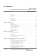
1 Unit Identification Overview Figure 1-9 and Figure 1-10 show the various components of the MicroCell and PicoCell systems.
Unit Identification – continued 1 Figure 1-10: General Block Diagram Showing the Unit, Site I/O Interface, and External Items (MicroCell Unit Shown) DC POWER RGPS SPAN SITE I/O INTERFACE MICROCELL ONLY ANT RX ANT TX/RX PHONE (MODEM) MICROCELL ONLY AC POWER MIB TERMINATOR DEC 2000 CUSTOMER INPUTS SCt300 BTS Hardware Installation, ATP and FRU Procedures PRELIMINARY 1-23
1 Unit Identification – continued Figure 1-11: Microcell and Picocell Unit MICROCELL UNIT PICOCELL UNIT Figure 1-12: Site I/O Junction Box and Cable 1-24 SCt300 BTS Hardware Installation, ATP and FRU Procedures PRELIMINARY DEC 2000
Unit Identification – continued 1 Figure 1-13: Primary Surge Suppressor (Optional) Figure 1-14: AC Installation Box (Optional) DEC 2000 SCt300 BTS Hardware Installation, ATP and FRU Procedures PRELIMINARY 1-25
1 Unit Identification – continued Figure 1-15: Mounting Bracket for both Microcell and Primary Surge Suppressor Figure 1-16: Mounting Bracket for Picocell 1-26 SCt300 BTS Hardware Installation, ATP and FRU Procedures PRELIMINARY DEC 2000
Unit Identification – continued 1 Figure 1-17: Adapters for Rack Mounting DEC 2000 SCt300 BTS Hardware Installation, ATP and FRU Procedures PRELIMINARY 1-27
1 Unit Identification – continued Figure 1-18: Adapters for Pole Mounting BUCKLESTRAP CHANNEL CLAMP UPPER CHANNEL EXTRUSION SEE DETAIL A CHANNEL CLAMP LOWER CHANNEL EXTRUSION DETAIL A SEE DETAIL A BUCKLESTRAP CHANNEL EXTRUSION CHANNEL CLAMP 1-28 SCt300 BTS Hardware Installation, ATP and FRU Procedures PRELIMINARY DEC 2000
Unit Identification – continued 1 Figure 1-19: Adapter for Ceiling Mounting (Optional) Figure 1-20: Installation Handles for Lifting Unit (Optional) Figure 1-21: Short Duration Battery (Optional) DEC 2000 SCt300 BTS Hardware Installation, ATP and FRU Procedures PRELIMINARY 1-29
1 Unit Identification – continued Figure 1-22: Front and Back Solar Covers for MicroCell FRONT COVER BACK COVER Figure 1-23: Front and Back Solar Covers for Surge Suppressor FRONT COVER BACK COVER 1-30 SCt300 BTS Hardware Installation, ATP and FRU Procedures PRELIMINARY DEC 2000
Unit Identification – continued 1 Figure 1-24: Front and Back Fin Covers for MicroCell and PicoCell (PicoCell shown) BACK COVER FRONT COVER 0149–O_IL.
1 Installation and ATP Order Installation Order The pieces of the MicroCell, PicoCell and Primary Surge Suppressor units should be installed in the following order. 1. Unpack and inspect hardware. 2. Install mounting hardware and bracket(s). 3. Install back solar cover to mounting bracket (required for outdoor installations and optional for indoor applications). 4. Install back fin cover to unit (required for indoor installations). 5. Install RGPS. 6. Prepare site cabling. 7.
Installation and ATP Order – continued 14. 15. 16. 17. 18. 19. 20. 1 Test cable calibration. Create CAL file. RF path audit. TX and RX Acceptance tests. Generate an ATP Report. Copy LMF CAL file to CBSC. Terminate LMF session/leave the site. Frequency Hopping Pilot Beacon ATP Order The Frequency Hopping Pilot Beacon (FHPB) ATP for the MicroCell and PicoCell units is performed in the following sequence: 1. Create CAL file. 2. RF path audit. 3. TX Acceptance tests. 4. Generate an ATP Report. 5.
1 Installation and ATP Order – continued Notes 1-34 SCt300 BTS Hardware Installation, ATP and FRU Procedures PRELIMINARY DEC 2000
Chapter 2: Site Preparation Table of Contents DEC 2000 Site Preparation Overview . . . . . . . . . . . . . . . . . . . . . . . . . . . . . . . . . . . . . . . . . Overview . . . . . . . . . . . . . . . . . . . . . . . . . . . . . . . . . . . . . . . . . . . . . . . . External Installation Versus Internal Installation . . . . . . . . . . . . . . . . . . Verifications and Procedures . . . . . . . . . . . . . . . . . . . . . . . . . . . . . . . . . Site Manager . . . . . . . . . . . . . . . . . . . . . . . .
Table of Contents – continued Notes 2 SCt300 BTS Hardware Installation, ATP and FRU Procedures PRELIMINARY DEC 2000
Site Preparation Overview Overview This chapter provides the procedures and information to verify that the site is ready to have the equipment installed. It also provides procedures to ensure the safety of the installation personnel, protect the equipment from damage, and verify the site layout parameters. External Installation Versus Internal Installation The MicroCell and PicoCell systems can be installed outdoors (external) or indoors (internal).
Site Inspections Inspection Overview Inspect the site to verify that the necessary equipment has been properly installed. Also, as part of the inspection, verify that the equipment is adequate to support the Motorola equipment. Not all inspections may apply to every site. The site characteristics determine which inspections apply. 2 NOTE Installation of ancillary equipment (e.g., power supplies, terminal blocks, etc.) may be the responsibility of the installer.
Site Inspections – continued Structural Inspections and Verifications 2 Wall loading capacity Verify with the site manager that the wall loading capacity has been previously checked by a qualified Civil Engineer and meets the specifications stated in the site-specific documentation. Pole loading capacity Verify with the site manager that the pole loading capacity has been previously checked and meets the specifications stated in the site-specific documentation.
Site Inspections – continued Fire Fighting Procedures Cellular infrastructure equipment contains various materials which can decompose into toxic compounds during intense heat. When fire fighting conditions are severe, wear full protective clothing, including helmet, self–contained, positive pressure or pressure demand breathing apparatus, bunker coat and pants, bands around arms, waist and legs, face mask, and protective covering for exposed areas of the head.
Site Inspections – continued Alarms Verify with the site manager that any of the following alarms called out in the site-specific documentation have been installed and previously checked for meeting the site-specific documentation specifications. S vandalism S surface water S intrusion S fire S building high/low temperatures S any customer-specific options. The interface of the alarms to the Motorola equipment will be part of the cell site equipment installation.
Prepare Site for the Arrival of the Equipment Description 2 This information covers various topics not all of which are needed at every site. Based on the site characteristics execute the steps that apply to your site. Before installing the equipment, do the following to ensure the safety of installation personnel and to protect the equipment.
Prepare Site for the Arrival of the Equipment – continued Procedure to Prepare the Site for the Equipment 2 Table 2-1: Procedure to Prepare the Site for the BTS Step Action 1 If some type of protective padding is available install it around any existing equipment at the site that could be damaged during installation of the units. 2 Hang plastic sheets around intended work areas to prevent dust and debris from damaging co-located equipment during installation.
Dimensions and Clearances 2 MicroCell and PicoCell Overview This information covers the dimensions and clearances associated with the MicroCell and PicoCell Units. Dimensions and Clearances Table 2-2, Table 2-3, Figure 2-2 through Figure 2–7 show the installed dimensions and recommended clearances for each item. Table 2-2: Installation Dimensions for the MicroCell and PicoCell Units 2-8 Item Height Width Depth Weight MicroCell (fully installed) 730 mm 28.76 in. 590 mm 23.25 in. 254 mm 10.
Dimensions and Clearances – continued Table 2-3 Minimum Clearances MicroCell and PicoCell Units Vertical Mounting Item Front Back Left Right Top Bottom Installation and Maintenance Requirements 600 mm 23.62 in. 0 100 mm 3.93 in. 200 mm 7.87 in. 0 0 Functional Requirements (with solar cover) 0 0 100 mm 3.93 in. 200 mm **50 mm 1.96 in. **50 mm 1.96 in.
Dimensions and Clearances – continued Unit Dimensions The unit dimensions are shown below. 2 Figure 2-2: Overall Dimensions of MicroCell and PicoCell Units MicroCell Unit 450mm (17.71in.) 254 mm (10.01 in.) 730mm (28.76 in.) 590mm (23.22in.) 150mm (5.90in.) 590 mm (23.25 in.) PicoCell Unit 450mm (17.71in.) 500mm (19.68in.) 144mm (5.66in.) 510mm (20.08 in.) 525mm (20.66in.) 110mm (4.33in.
Dimensions and Clearances – continued Figure 2-3: Overall Dimensions of Primary Surge Suppressor Without Solar Cover 2 465 mm (18.32 in.) 125 mm (4.93 in.) 510 mm (20.08 in) With Solar Cover 254 mm (10.01 in.) 730mm (28.76 in.) 590 mm (23.25 in.
Dimensions and Clearances – continued Unit Clearances The unit clearances are shown below.
Dimensions and Clearances – continued Figure 2-5: Installation and Functional Clearances for MicroCell Units (without Solar Covers) 2 MICROCELL WITHOUT SOLAR COVERS 50 mm Air Intake (Functional) 600 mm from front of unit for FRU installation and removal 200 mm clearance for tool access 100 mm clearance for installation handles 50 mm air exhaust area 50 mm air intake area DEC 2000 SCt300 BTS Hardware Installation, ATP and FRU Procedures PRELIMINARY 2-13
Dimensions and Clearances – continued Figure 2-6: Installation and Functional Clearances for PicoCell Units (without Solar Covers) PICOCELL WITHOUT SOLAR COVERS 2 50 mm Air Intake Area (Functional) 600 mm from front of unit for FRU installation and removal 200 mm clearance for tool access 100 mm clearance for installation handles 50 mm air exhaust area 50 mm air intake area 0196–O_IL.
Dimensions and Clearances – continued Figure 2-7: Installation and Functional Clearances for Primary Surge Suppressor (without Solar Covers) PRIMARY SURGE SUPPRESSOR WITHOUT SOLAR COVERS 2 DEC 2000 200 mm clearance for tool access 200 mm clearance for tool access 600 mm from front of unit for unit installation and removal SCt300 BTS Hardware Installation, ATP and FRU Procedures PRELIMINARY 2-15
Dimensions and Clearances – continued Figure 2-8: Installation and Functional Clearances for Primary Surge Suppressor (with Solar Covers) 2 PRIMARY SURGE SUPPRESSOR WITH SOLAR COVERS 2-16 200 mm clearance for tool access 200 mm clearance for tool access 600 mm from front of unit for FRU installation and removal SCt300 BTS Hardware Installation, ATP and FRU Procedures PRELIMINARY DEC 2000
Dimensions and Clearances – continued Figure 2-9: Installation and Functional Clearances for PicoCell Unit Mounted to Ceiling For PicoCell horizontal mounting assume unit is in a volume (400H x 600W x 500D) 100mm as shown below. Additional clearances are measured from edge of the volume.
Dimensions and Clearances – continued Figure 2-10: Concept of Functionality Clearances for MicroCell and PicoCell Units 2 THIS ILLUSTRATION SHOWS THE CONCEPT OF HOW THE AREA ABOVE AND BELOW THE SCt340 BTS SHOULD BE AT LEAST 25% UNOBSTRUCTED. THERE IS NO BOX AROUND THE UNIT.
Chapter 3: Installing Mounting Bracket and Remote GPS Table of Contents 3 DEC 2000 Overview . . . . . . . . . . . . . . . . . . . . . . . . . . . . . . . . . . . . . . . . . . . . . . . . . . . . . . . Overview . . . . . . . . . . . . . . . . . . . . . . . . . . . . . . . . . . . . . . . . . . . . . . . . Procedure order . . . . . . . . . . . . . . . . . . . . . . . . . . . . . . . . . . . . . . . . . . . 3-1 3-1 3-1 Unpacking the Equipment and Inspecting for Damage . . . . . . . . . . . . . . . . . .
Table of Contents – continued Notes 3 SCt300 BTS Hardware Installation, ATP and FRU Procedures PRELIMINARY DEC 2000
Overview Overview This chapter provides the information and procedures to: S S S S Unpack the equipment and inspect for damage. Install rack, pole or ceiling adapters. Install the mounting bracket on a wall, pole, rack or ceiling. Attach the unit and covers to the mounting bracket. 3 Procedure order The process of installing the mounting bracket and Remote GPS receiver requires that the following procedures be completed in the order shown. 1. Unpack the equipment and inspect for damage. 2.
Unpacking the Equipment and Inspecting for Damage Objective The objective of this procedure is to unpack the equipment and inspect it for damage. How System is Packed A unit is shipped in two boxes. Box 1 contains site installation specific components and box 2 contains the unit itself. All of the following are shipped in box 1.
Unpacking the Equipment and Inspecting for Damage – continued Inspect items for: S S S S S S S DEC 2000 dents scratches bent pins in connectors squareness of bracket damage to heatsink fins isolating pads, washers on mounting bracket 3 frayed cabling or chafed connectors SCt300 BTS Hardware Installation, ATP and FRU Procedures PRELIMINARY 3-3
Attaching the Mounting Bracket to a Wall Objective The objective of this procedure is to attach the mounting bracket on a concrete wall. CAUTION For all applications always consult a licensed Civil Engineer to determine the exact (Zone 3 and/or Zone 4) compliance of your specific site. 3 NOTE If your site requires the optional Primary Surge Suppressor, then you must install two mounting brackets.
Attaching the Mounting Bracket to a Wall – continued Required Tools and Materials for Concrete Wall Mounting CAUTION Do not use toggle bolts in sheet rock (dry wall). They will not hold the system and they will damage the wall. Due to the many types of walls that the BTS could potentially be mounted to, it is impossible to detail all types in the context of this manual.
Attaching the Mounting Bracket to a Wall – continued Procedure to Drill Holes in the Wall WARNING Safety glasses, dust masks, and ear plugs must be worn by all installation personnel, including those in the immediate vicinity of the personnel operating the drilling equipment. 3 Table 3-2: Procedure to Drill Holes in the Wall for Mounting Bracket Installation Step Action 1 Verify with the site manager that the wall has been previously checked and is capable of supporting the weight of the system.
Attaching the Mounting Bracket to a Wall – continued Securing Mounting Bracket to a Wall Refer to Figure 3-1 and Figure 3-2 and follow the procedure in Table 3-3 to secure the mounting bracket to a wall. Table 3-3: Procedure to Secure the Mounting Bracket to a Wall Step Action * IMPORTANT 3 Use the shoulder washers attached to the mounting bracket in each mounting hole to electrically isolate the mounting bracket from the wall. 1 Insert a Hilti anchor into each mounting hole.
Attaching the Mounting Bracket to a Wall – continued Figure 3-2: Securing Mounting Bracket to a Wall 3 PLACE SCREW THROUGH HOLES LAG SCREW (FROM TOP TO BOTTOM) LAG SCREW, AND PLASTIC SHOULDER WASHER THREADED INTO PILOT HOLE THROUGH MOUNTING PLATE. É É É ÄÄ É ÄÄ ÉÉÉ É É É STUD WALL BRACKET (FOR CLARITY, THE REST OF THE BRACKET IS NOT SHOWN) CONCRETE ANCHOR (FROM TOP TO BOTTOM) BOLT AND PLASTIC SHOULDER WASHER THREADED INTO ANCHOR THROUGH MOUNTING BRACKET ÉÉ ÉÉ ÉÉ Ä ÉÉÉ ÉÉ Ä ÉÉÉ ÉÉ ÉÉ 0156–O_IL.
Attaching the Mounting Bracket to a Ceiling Objective The objective of this procedure is to attach the adapter and mounting bracket to a ceiling. IMPORTANT * You can only mount the Picocell to a ceiling. 3 Due to the many types of ceilings that the BTS may be mounted to, it is impossible to detail all types in the context of this manual.
Attaching the Mounting Bracket to a Ceiling – continued Figure 3-3: Picocell Ceiling Mounting Bracket 3 MOUNTING PROVISIONS – EXACT USE IS SITE SPECIFIC Tools and Materials for Installing the Mounting Bracket on a Ceiling Concrete ceiling The following tools and materials are required to properly and safely install the the ceiling adapter on a concrete ceiling. Table 3-4: Tools and Materials for Concrete Ceiling Hand Tools Materials Power Tools 15/16-in. (23.
Attaching the Mounting Bracket to a Ceiling – continued Securing Mounting Bracket to Adapter Once the adapter has been secured to the ceiling, the procedure in Table 3-5 must be followed to mount the bracket to the adapter. Table 3-5: Procedure to Secure the Mounting Bracket to the Adapter Step Action 1 Verify that isolating pads and bracket–mounted shoulder washers are installed on the bracket. If not, contact the site manager.
Attaching the Mounting Bracket to a Pole Objective The objective of this procedure is to attach the mounting bracket to a pole. WARNING The mounting pole structure must be reviewed for its ability to support the weight of the MicroCell [38.5 kg (84.7 lbs.)]; PicoCell [30.5 kg (67.1 lbs.)] and Primary Surge Suppressor [19.17 kg (42.26 lbs.)] under high winds, earthquakes, etc. 3 S Installing the BTS on an inadequate pole may result in serious personal injury even death or damage to the equipment.
Attaching the Mounting Bracket to a Pole – continued Procedure to Attach the Mounting Bracket to a Pole Follow the procedure in Table 3-7 to attach the mounting bracket to a pole. Table 3-7: Procedure for Attaching the Mounting Bracket to a Pole Step DEC 2000 Action 1 Verify that the isolator pads are in place on the bracket. 2 Verify the safety of the installation location. 3 Place the bucklestrap through the channel clamp as shown in Figure 3-5.
Attaching the Mounting Bracket to a Pole – continued Figure 3-5: Pole Adapter and Straps BUCKLESTRAP PART NUMBER 4209993S04 3 CHANNEL CLAMP PART NUMBER 4209992S01 UPPER CHANNEL EXTRUSION PART NUMBER 0709991S02 CHANNEL CLAMP PART NUMBER 4209992S01 BUCKLESTRAP CHANNEL EXTRUSION CHANNEL CLAMP LOWER CHANNEL EXTRUSION PART NUMBER 0709991S03 SIDE VIEW OF CHANNEL CLAMP AND BAND 0159–O_IL.
Attaching the Mounting Bracket to a Pole – continued Figure 3-6: Attaching Mounting Bracket to a Pole 3 M6x19 SCREWS PART NUMBER 0387541C03 DEC 2000 SCt300 BTS Hardware Installation, ATP and FRU Procedures PRELIMINARY 3-15
Attaching the Mounting Bracket to a Rack Objective The objective of this procedure is to attach the mounting bracket to a 19-in. rack. Rack must conform to EIA–RS–310–C or JIS–C–6010 standards. 3 Tools and Materials for Installing the Mounting Bracket on a Rack The following tools and materials are required to properly and safely install the mounting bracket on a rack. Table 3-8: Tools and Materials for Rack Mounting Hand Tools Materials Power Tools Torque driver wrench, 1/4–in.
Attaching the Mounting Bracket to a Rack – continued Table 3-9: Procedure to Attach the Mounting Bracket to a Rack Step Action 6 Use two machine screws (customer supplied) to attach the lower rack adapter to the rack. 7 Use a T30 Torx tamper bit to torque the screws connecting the mounting bracket to the upper and lower adapters. Torque to 5.0 N–M.
Attaching Mounting Bracket to a Rack – continued Figure 3-7: Attaching the Mounting Bracket to a Rack A=MACHINE SCREW 12–24 5/8 IN.
Attaching Back Solar Cover to Mounting Bracket Objective The objective of this procedure is to attach the back solar cover to the mounting bracket. When to Use the Cover Solar Covers are required in all outdoor applications 3 Required tools The following tools are required to attach the back solar cover to the mounting bracket. S Torque driver wrench, 1/4–in.
Attaching Back Solar Cover to Mounting Bracket – continued Figure 3-8: Attaching MicroCell Back Solar Cover to Mounting Bracket 3 M6 SCREWS 0309959S06 3-20 SCt300 BTS Hardware Installation, ATP and FRU Procedures PRELIMINARY DEC 2000
Remote GPS Head Installation Objective The objective of this procedure is to show how to install the Remote Global Positioning System (RGPS) head. Tools and Materials One RGPS Head (Motorola Part Number 0186012H03) is required to do this procedure. Installation Procedure CAUTION The RGPS head must not make contact with any metal surface other than the provided hardware. Use only the equipment provided to mount the RGPS head. Failure to do so could damage the RGPS head.
Remote GPS Head Installation – continued Table 3-11: Installing the RGPS Head Step 5 Action ! CAUTION To avoid binding the RGPS interface cable, cable turn the pipe, pipe not the RGPS head, head while tightening. tightening Insert the pipe into the threaded neck on the RGPS head and hand tighten. 6 3 Place the assembly into the mounting brackets and secure with the two clamp brackets, U–bolts and nuts as shown in Figure 3-9.
Chapter 4: Preparing Site Cabling for Sites Equipped with Customer–Supplied Site I/O Interface Table of Contents Cabling Overview . . . . . . . . . . . . . . . . . . . . . . . . . . . . . . . . . . . . . . . . . . . . . . . . Overview . . . . . . . . . . . . . . . . . . . . . . . . . . . . . . . . . . . . . . . . . . . . . . . . Configurations Supported . . . . . . . . . . . . . . . . . . . . . . . . . . . . . . . . . . . Cabling Installation Order . . . . . . . . . . . . . . . . . . . . . . . . . . . . .
Table of Contents – continued Connecting the RGPS Cable to the Site I/O Interface . . . . . . . . . . . . . . Connecting the Span Line Cable to the Site I/O Interface . . . . . . . . . . Connecting a Phone Line to the Site I/O Interface (Modem Support) . 4-29 4-29 4-30 RGPS Cabling for Multi–BTS Configurations . . . . . . . . . . . . . . . . . . . . . . . . . Overview . . . . . . . . . . . . . . . . . . . . . . . . . . . . . . . . . . . . . . . . . . . . . . . . Background . . . . . . . . . . . . . . .
Cabling Overview Overview This chapter provides the procedures to prepare the BTS site cabling, but not attach it to the unit. Chapter 6 shows the scope of work for unit cabling. You will connect cables to the site and route them to the BTS location. You will attach the cables to the unit in Chapter 6. Repeat cabling installation as necessary for each unit at the BTS. NOTE Cabling is one of the most noticeable aspects of workmanship.
Cable Descriptions Cable Descriptions and Part Numbers Table 4-1 gives the cable descriptions and part numbers for the cables used to install the BTS. The following cables are necessary for sites equipped with the customer–supplied Site I/O Interface and the Primary Surge Suppressor. Table 4-1: Cable Descriptions and Part Numbers Cable Qty. Part Number A 1 3087701C02 Ground cable, 8 -AWG, insulated copper wire. Requires one ring lug connector. Used for Primary Surge Suppressor Installation.
Cable Descriptions – continued Table 4-1: Cable Descriptions and Part Numbers Cable Qty. Part Number O 1 Customer Supplied P 1 3087416C19 SU cable, 105 mm Q N/A* 3088120C01 SU RF cable, long (part of kits SGEN4062A, SGEN4061A, SGEN4064A, SGEN4063A, SGEN4066A, SGEN4065A, SGEN4068A, SGEN4067A, SGEN4070A and SGEN4069A). R N/A* 3088120C02 SU RF cable, short (part of kits SGEN4066A and SGEN4065A) S 1–4 3087854C02 AC input power cable. 14 AWG. 5m. Designed for 120–240 VAC power input.
Cable Descriptions – continued Motorola Kits for Multi–Unit Installations Table 4-2 through Table 4-11 gives the Motorola Kit numbers, cable descriptions and part numbers for the Motorola kits required to perform a multi–unit installation. Several kits are available depending upon the carrier installation. Table 4-2: Microcell Expansion Kit for Units 1 to 2 Short MIB A (Cubicle) – T448AL Cable Qty.
Cable Descriptions – continued Table 4-6: Microcell/Picocell Expansion Kit for Units 2 to 3 Current 2m MIB B – T448AR Cable Qty. Motorola Part Number Description A 1 3087701C02 Ground cable, 8 -AWG, insulated copper wire. Requires one ring lug connector.
Cable Descriptions – continued Table 4-9: Microcell/Picocell Expansion Kit for Units 3 to 4 Longer 5M MIBs B and C – T448AU Cable Qty. Motorola Part Number Description n/a 2 5882106P01 50 Ohm Antenna Terminator A 1 3087701C02 Ground cable, 8 -AWG, insulated copper wire. Requires one ring lug connector.
Cable Descriptions – continued Motorola Kits for RGPS Cabling Table 4-12 and Table 4-13 show the contents of Motorola kits SGKN4351A and SGKN4352A. These kits are necessary for RGPS cabling between multiple BTS locations. Table 4-12: RGPS Synchronization Cable Kit – SGKN4351A Cable Qty. Motorola Part Number Description X 1 3086039H18 RGPS Sync Cable, 2000 ft. n/a 2 5864461A03 Fitting, liquid tight.
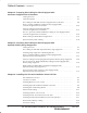
Site Cabling for BTS With Customer–Supplied Site I/O Interface Preparing Site Cabling Scope of Work Figure 4-1 through Figure 4-8 shows the scope of work to be performed for preparing the site cabling with the customer–supplied Site I/O Interface. Chapter 6 shows the scope of work for unit cabling.
Site Cabling for BTS With Customer–Supplied Site I/O Interface – continued Figure 4-2: Site Cabling for Two Microcells U/1(DC POWER) S/1(AC POWER) B/1 (GROUND) D/1(ANTENNA) MICROCELL 1 Y/1(GROUND) DC POWER AC INSTALL BOX (SEE NOTE 3) LA AC POWER ANT 1 TX/RX LA GROUND P/1 (SU) M/1 (RGPS) N/1 (SPAN) DSU LA SPAN O/1 (CUSTOMER INPUT) CUSTOMER INPUTS Z/1 (SITE I/O CABLE) SEE NOTES 1 AND 2 SITE I/O INTERFACE Q/1 (SU) RGPS LA V/1 (PHONE) LA 4 PHONE (MODEM) E/1 (MIB) OR K/1 (MIB) U/1(DC POW
Site Cabling for BTS With Customer–Supplied Site I/O Interface – continued Figure 4-3: Site Cabling for Three Microcells F/1 (MIB) OR I/1 (MIB) U/1(DC POWER) U/1(DC POWER) S/1 (AC POWER) DC POWER AC INSTALL BOX (SEE NOTE 3) D/1(ANTENNA) LA ANT 4 TX/RX LA ANT 3 RX MICROCELL 3 D/1(ANTENNA) LA S/1 (AC POWER) AC INSTALL BOX (SEE NOTE 3) AC POWER LA AC POWER B/1 (GROUND) MICROCELL 1 D/1(ANTENNA) Y/1(GROUND) Y/1(GROUND) GROUND 2X R/1 (SU) N/1 (SPAN) 2X Q/1 (SU) Q/1 (SU) GROUND SITE I/O INT
Site Cabling for BTS With Customer–Supplied Site I/O Interface – continued Figure 4-4: Site Cabling for Four Microcells F/1 (MIB) OR I/1 (MIB) U/1(DC POWER) U/1(DC POWER) S/1 (AC POWER) MICROCELL 4 DC POWER AC INSTALL BOX (SEE NOTE 3) D/1(ANTENNA) S/1 (AC POWER) LA AC INSTALL BOX (SEE NOTE 3) AC POWER B/1 (GROUND) MICROCELL 1 D/1(ANTENNA) Y/1(GROUND) GROUND Y/1(GROUND) R/1 (SU) Q/1 (SU) 2X 2X R/1 (SU) W/1 (SPAN) ANT 1 TX/RX LA GROUND M/1 (RGPS) Q/1 (SU) RGPS LA DSU LA SPAN Q/1 (
Site Cabling for BTS With Customer–Supplied Site I/O Interface – continued Figure 4-5: Site Cabling for One Picocell U/1(DC POWER) S/1 (AC POWER) B/1 (GROUND) PICOCELL 1 D/1(ANTENNA) Y/1(GROUND) DC POWER AC INSTALL BOX (SEE NOTE 2) LA AC POWER ANT A TX/RX LA GROUND P/1 (SU) M/1 (RGPS) N/1 (SPAN) LA RGPS DSU LA SPAN O/1 (CUSTOMER INPUT) CUSTOMER INPUTS Z/1 (SITE I/O CABLE) SEE NOTE SITE I/O INTERFACE V/1 (PHONE) LA PHONE (MODEM) 4 KEY B/1(ANTENNA) LEGEND LA = Lightning Arrestor NAME N
Site Cabling for BTS With Customer–Supplied Site I/O Interface – continued Figure 4-6: Site Cabling for Two Picocells U/1(DC POWER) S/1 (AC POWER) B/1 (GROUND) PICOCELL 1 DC POWER AC INSTALL BOX (SEE NOTE 3) D/1(ANTENNA) Y/1(GROUND) GROUND Q/1 (SU) RGPS LA LA DSU O/1 (CUSTOMER INPUTS) Z/1 (SITE I/O CABLE) SEE NOTE SITE I/O INTERFACE AC POWER ANT 1 TX/RX LA M/1 (RGPS) N/1 (SPAN) LA V/1 (PHONE) LA SPAN CUSTOMER INPUTS 4 PHONE (MODEM) H/1 (MIB) OR L/1 (MIB) OR U/1(DC POWER) S/1 (AC
Site Cabling for BTS With Customer–Supplied Site I/O Interface – continued Figure 4-7: Site Cabling for Three Picocells F/1 (MIB) OR I/1 (MIB) U/1(DC POWER) S/1 (AC POWER) U/1(DC POWER) DC POWER AC INSTALL BOX (SEE NOTE 3) LA S/1 (AC POWER) DC POWER AC INSTALL BOX (SEE NOTE 3) AC POWER LA AC POWER PICOCELL 3 D/1(ANTENNA) ANT 4 TX/RX LA Y/1(GROUND) B/1 (GROUND) PICOCELL 1 D/1(ANTENNA) GROUND Q/1 SU Y/1(GROUND) R/1 (SU) 2X 2X R/1 (SU) Q/1 (SU) GROUND M/1 (RGPS) N/1 (SPAN) Q/1 (SU) DSU
Site Cabling for BTS With Customer–Supplied Site I/O Interface – continued Figure 4-8: Site Cabling for Four Picocells F/1 (MIB) OR I/1 (MIB) U/1(DC POWER) S/1 (AC POWER) PICOCELL 4 U/1(DC POWER) DC POWER DC POWER AC INSTALL BOX (SEE NOTE 3) D/1(ANTENNA) LA AC POWER D/1(ANTENNA) B/1 (GROUND) GROUND Y/1(GROUND) R/1 (SU) 2X LA PICOCELL 1 Y/1(GROUND) Q/1 SU AC INSTALL BOX (SEE NOTE 3) AC POWER ANT 4 TX/RX LA S/1 (AC POWER) R/1 (SU) GROUND M/1 (RGPS) W/1 (SPAN) RGPS LA 2X Q/1 (SU) A
Power, Ground, and Battery Cabling for Sites Equipped With Customer–Supplied Site I/O Interface Objective The objective of this procedure is to install the power, earth ground, and battery cabling for one or more Microcell or Picocell units at a site equipped with customer–supplied Site I/O Interface. WARNING Dangerous voltages, capable of causing death, are present in this equipment. Use extreme caution when handling and testing this equipment.
Power, Ground, and Battery Cabling for Sites Equipped With Customer–Supplied Site I/O Interface – continued Cables Needed Table 4-14 provides the quantity and description of the cables needed. Table 4-14: Cables Needed for Power, Earth Ground, and Battery Connections Cable Qty. Part Number Description S 1–4 3087854C02 AC input cable, 14 AWG, 5 m, is designed for 88–260 VAC power input. U 1–4 3087854C04 DC input cable, 14 and 22 AWG, 5 m, is designed for 20 to 40 VDC power input.
Power, Ground, and Battery Cabling for Sites Equipped With Customer–Supplied Site I/O Interface – continued DC Input Cable Information The information for the DC input cable(s) (Cable U) is given in Figure 4-10. Figure 4-10: DC Input Cable Connector Information A B D SOCKET POSITION ON CABLE CONNECTOR SHOWN C Table 4-16: DC Input Cable Information Connector Wire Color Description Comments A Yellow Switch A No connection B Red Positive Connect to positive terminal of supply.
Power, Ground, and Battery Cabling for Sites Equipped With Customer–Supplied Site I/O Interface – continued Table 4-18: Procedure to Install AC Input Cable(s) (Indoor Applications) Step Action 1 If you will not use the AC Installation box, remove the male connector (with pins) from the AC input power cable (cable S). 2 Connect the loose wires of cable S (AC input cable) to the customer defined AC power source. Refer to Table 4-15 for wiring information.
Power, Ground, and Battery Cabling for Sites Equipped With Customer–Supplied Site I/O Interface – continued Figure 4-11: AC Installation Box TO GROUND CONNECTOR ON INSIDE OF DOOR GREEN TO MICROCELL/ PICOCELL LOCATION 3 GROUND NEUTRAL WHITE 2 1 CUSTOMER AC INPUT LINE BLACK AC POWER CABLE CONNECTOR 1–IN AC CONDUIT 4 NOTE: Shown with door removed for clarity Table 4-21: Procedure to Install DC Input Cable(s) Step 4-20 Action 1 Connect the loose wires of cable U (DC input cable) to the customer d
Antenna Cabling for Sites Equipped With Customer–Supplied Site I/O Interface Objective The objective of this procedure is to install the cabling for the antenna(s). This cabling is installed between one or more units and the customer–supplied lightning arrestor(s). Cable Labels The cable designations are referenced to Table 4-1 in the “Cable Description” area of this chapter. Equipment Needed Table 4-22 provides the quantities and descriptions of the cables.
Antenna Cabling for Sites Equipped With Customer–Supplied Site I/O Interface – continued Procedure to Install Antenna Cabling for One Antenna IMPORTANT * You must install lightning arrestors for all outdoor installations. Route the antenna cable between the unit and the customer–supplied lightning arrestor. If a lighting arrestor is not required, route the cabling directly to the antenna. Refer to Figure 4-12 and Table 4-23.
Antenna Cabling for Sites Equipped With Customer–Supplied Site I/O Junction Box – continued Figure 4-14: Antenna Cabling for Maximum of Four Microcells or Picocells MICROCELL/ PICOCELL 4 C/1(ANTENNA) MICROCELL/ PICOCELL 3 C/1(ANTENNA) LA LA ANT 4 TX/RX ANT 3 TX/RX MICROCELL/ PICOCELL 1 C/1(ANTENNA) MICROCELL/ PICOCELL 2 C/1(ANTENNA) LA LA ANT 1 TX/RX ANT 2 TX/RX KEY B/1(ANTENNA) LIGHTNING LA = ARRESTOR NAME NUMBER OF CABLES LABEL 4 DEC 2000 SCt300 BTS Hardware Installation, ATP and FRU
Site I/O , Span Line, RGPS and Modem Cabling for Sites Equipped With Customer–Supplied Site I/O Interface Objective The objective of this procedure is to install the Site I/O cable between the Site I/O junction box and the customer–supplied Site I/O interface. This procedure also covers the installation of the site cabling of the span line, RGPS and modem cabling to the site I/O interface.
Site I/O , Span Line, RGPS and Modem Cabling for Sites Equipped With Customer–Supplied Site I/O Interface – continued Procedure to Install Site I/O Cable Between Site I/O Junction Box and Site I/O Interface Route the Site I/O junction box cable from the unit location(s) to the Site I/O Extender Cable (cable Z). Route cable Z to the Site I/O interface. Connect the appropriate connectors within the Site I/O interface. Refer to Figure 4-15 and Table 4-25.
Site I/O , Span Line, RGPS and Modem Cabling for Sites Equipped With Customer–Supplied Site I/O Interface – continued Pin and Signal Information for Site I/O Cabling Table 4-25 gives the pin and signal information for the Site I/O cable.
Site I/O , Span Line, RGPS and Modem Cabling for Sites Equipped With Customer–Supplied Site I/O Interface – continued Table 4-25: Pin/Signal Information for Site I/O Cable BTS Interface Sync Forward Span (Network) Wire/Stripe Color Description Brown/Grey Data from Head – Brown/White Data from Head + Red/Black Data to Head – Red/Brown Data to Head + Red/Orange 1 PPS from Head – Red/Yellow 1 PPS from Head + Red/Green 1 PPS to Head – Red/Blue 1 PPS to Head + Red/Purple RGPS 28V Red/Grey
Site I/O , Span Line, RGPS and Modem Cabling for Sites Equipped With Customer–Supplied Site I/O Interface – continued Table 4-25: Pin/Signal Information for Site I/O Cable BTS Interface Span (Redundant) 4 Phone (Modem) Wire/Stripe Color Description Yellow/Green RX TIP Primary (Redundant) Yellow/Blue RX RING Primary (Redundant) Yellow/Purple TX TIP Primary (Redundant) Yellow/Grey TX RING Primary (Redundant) Yellow/White RX TIP Secondary (Redundant) Green/Black RX RING Secondary (Redundant)
Site I/O , Span Line, RGPS and Modem Cabling for Sites Equipped With Customer–Supplied Site I/O Interface – continued Connecting the RGPS Cable to the Site I/O Interface The RGPS (cable M) is connected to the Site I/O interface (Sync Forward) of the BTS. Table 4-26 provides the Sync Forward to RGPS connections.
Site I/O , Span Line, RGPS and Modem Cabling for Sites Equipped With Customer–Supplied Site I/O Interface – continued Connecting a Phone Line to the Site I/O Interface (Modem Support) The unit provides a two–wire analog phone line interface for modem support. The unit Tip and Ring signals are connected to the external phone line Tip and Ring.
RGPS Cabling for Multi–BTS Configurations Overview This procedure gives information to connect multiple units for both RGPS (synchronous) and HSO (non–synchronous) configurations. Background The RGPS only connects to the first unit of a multi–unit system. This first unit sends timing signals to all other units in a multi–unit system. You only need to connect the first units of each BTS to each other. This allows “sharing” of a single RGPS antenna between several single or multi–unit BTSs.
RGPS Cabling for Multi–BTS Configurations – continued Cable Diagram Figure 4-16 and Figure 4-17 both show the cabling for multi–unit configurations for both RGPS (sychronous) and HSO (non–synchronous). Procedure Connect the cables (Cable O) between the RGPS head (if used) and the site I/O junction box of each BTS. Refer to the cable run list in Table 4-30, Figure 4-16 and Figure 4-17.
RGPS Cabling for Multi–BTS Configurations – continued Figure 4-16: Site I/O Interface Cabling for RGPS (Synchronous) Configurations UNIT 4 UNIT 3 UNIT 2 UNIT 1 RGPS SPAN CUSTOMER INPUTS SITE I/O INTERFACE PHONE (MODEM) SITE I/O CABLE BTS 1 (SEE NOTE 1) UPSTREAM UNIT 3 UNIT 2 X UNIT 1 RGPS DAISY CHAIN CABLE MAXIMUM DISTANCE IS 1 KM (SEE NOTE 2) DOWNSTREAM SPAN BTS 2 (SEE NOTE 1) SITE I/O INTERFACE CUSTOMER INPUTS 4 PHONE (MODEM) SITE I/O CABLE UPSTREAM UNIT 2 X UNIT 1 RGPS DAISY CHAIN
RGPS Cabling for Multi–BTS Configurations – continued Figure 4-17: Site I/O Interface Cabling for HSO (Non–Synchronous) Configurations UNIT 4 UNIT 3 UNIT 2 UNIT 1 SPAN SITE I/O INTERFACE CUSTOMER INPUTS PHONE (MODEM) SITE I/O CABLE BTS 1 (SEE NOTE 1) UPSTREAM UNIT 3 UNIT 2 X UNIT 1 RGPS DAISY CHAIN CABLE MAXIMUM DISTANCE IS 600M (SEE NOTE 2 DOWNSTREAM SPAN BTS 2 (SEE NOTE 1) SITE I/O INTERFACE 4 CUSTOMER INPUTS PHONE (MODEM) SITE I/O CABLE UPSTREAM UNIT 2 X UNIT 1 RGPS DAISY CHAIN CABL
RGPS Cabling for Multi–BTS Configurations – continued Cable Connections For a full signal description of the Site I/O cable, refer to NO TAG in the “Site I/O, Span Line, RGPS and Modem Cabling” procedure. NOTE The pin number and wire color are based on the Site I/O cable. The pin number corresponds to pins on the Site I/O junction box connectors.
Span Line Daisy Chain Cabling Objective The objective of this procedure is to install span line cabling between multiple BTSs in an open daisy chain configuration. Background This feature allows BTSs to be linked together in an open daisy chain loop using a single T1/JT1/E1 span. This will reduce the number of spans necessary to support a JCDMA system and minimize unused channels. Each BTS may contain up to four units. A maximum of 12 BTSs may be combined in a single daisy chain.
Span Line Daisy Chain Cabling – continued Figure 4-18: Site I/O Interface Cabling for Span Line Daisy Chain Cabling RGPS SPAN BTS 1 (SEE NOTE 1) SITE I/O INTERFACE SITE I/O CABLE CUSTOMER INPUTS PHONE (MODEM) N SPAN LINE DAISY CHAIN CABLE SPAN BTS 2 (SEE NOTE 1) SITE I/O INTERFACE SITE I/O CABLE CUSTOMER INPUTS 4 PHONE (MODEM) N SPAN LINE DAISY CHAIN CABLE SPAN BTS 3 (SEE NOTE 1) SITE I/O INTERFACE SITE I/O CABLE CUSTOMER INPUTS PHONE (MODEM) N SPAN LINE DAISY CHAIN CABLE SPAN BTS 4 (SEE
Span Line Daisy Chain Cabling – continued Cable Connections Table 4-32 shows the cable run information for span line daisy chain cabling. For a full signal description of the Site I/O cable refer to NO TAG in the “Site I/O, Span Line, RGPS and Modem Cabling” procedure. NOTE The pin number and wire color are based on the Site I/O cable. The pin number corresponds to pins on the Site I/O junction box connectors.
Chapter 5: Preparing Site Cabling for Sites Equipped with Optional Primary Surge Suppressor Table of Contents Cabling Overview . . . . . . . . . . . . . . . . . . . . . . . . . . . . . . . . . . . . . . . . . . . . . . . . Overview . . . . . . . . . . . . . . . . . . . . . . . . . . . . . . . . . . . . . . . . . . . . . . . . Configurations Supported . . . . . . . . . . . . . . . . . . . . . . . . . . . . . . . . . . . Cabling Installation Order . . . . . . . . . . . . . . . . . . . . . . . . . . . . . . .
Table of Contents – continued Connecting Customer–Defined Inputs to the Primary Surge Suppressor Connecting the RGPS Cable to the Primary Surge Suppressor . . . . . . Connecting the Span Line Cable to the Primary Surge Suppressor . . . Connecting a Phone Line to the Primary Surge Suppressor (Modem Support) . . . . . . . . . . . . . . . . . . . . . . . . . . . . . . . . . . . . . . . . . . 5 5-30 5-30 5-31 5-31 RGPS Cabling for Multi–BTS Configurations Equipped with Optional Primary Surge Suppressor . .
Cabling Overview Overview This chapter provides the procedures to prepare the BTS site cabling for sites equipped with the optional Primary Surge Suppressor. Chapter 6 shows the scope of work for unit cabling. You will connect the cables to the site and route them to the location of the BTS. You will attach the cables to the unit during the unit cabling procedures in Chapter 6. Repeat cabling installation as necessary for each unit at the BTS.
Site Cabling for BTS With Optional Primary Surge Suppressor Preparing Site Cabling Scope of Work Figure 5-1 through Figure 5-8 shows the scope of work to be performed for preparing the site cabling with the optional Primary Surge Suppressor. Chapter 6 shows the scope of work for unit cabling.
Site Cabling for BTS With Optional Primary Surge Suppressor – continued Figure 5-2: Site Cabling for Two Microcells with Primary Surge Suppressor U/1(DC POWER) B/1 (GROUND) DC POWER A/1(GROUND) D/1 (ANTENNA 1) Q/1 (SU) MICROCELL 1 S/1 (AC POWER) O/1 (CUSTOMER CUSTOMER INPUTS) INPUTS P/1 (SU) SITE I/O INTERFACE SITE I/O CABLE N/1 (SPAN) M/1 (RGPS) V/1 (PHONE) SPAN RGPS PHONE (MODEM) T/1(AC POWER) AC POWER PRIMARY SURGE SUPPRESSOR E/1 (MIB) OR K/1 (MIB) C/1 (ANTENNA) ANT A RX C/1 (ANTENNA) ANT
Site Cabling for BTS With Optional Primary Surge Suppressor – continued Figure 5-3: Site Cabling for Three Microcells with Primary Surge Suppressor U/1(DC POWER) B/1 (GROUND) DC POWER A/1(GROUND) D/1 (ANTENNA 1) R/1 (SU) 2X 2X R/1 (SU) MICROCELL 1 S/1 (AC POWER) O/1 (CUSTOMER INPUTS) CUSTOMER INPUTS Q/1 (SU) N/1 (SPAN) SITE I/O M/1 (RGPS) INTERFACE SITE I/O CABLE Q/1 (SU) F/1 (MIB) OR I/1 (MIB) RGPS PHONE (MODEM) T/1(AC POWER) AC POWER PRIMARY SURGE SUPPRESSOR 5 C/1 (ANTENNA) ANT A RX C/1 (
Site Cabling for BTS With Optional Primary Surge Suppressor – continued Figure 5-4: Site Cabling for Four Microcells with Primary Surge Suppressor F/1 (MIB) OR I/1 (MIB) U/1(DC POWER) U/1(DC POWER) DC POWER R/1 (SU) Q/1 (SU) A/1(GROUND) 2X 2X R/1 (SU) MICROCELL 4 DC POWER B/1 (GROUND) MICROCELL 1 D/1 (ANTENNA 1) S/1 (AC POWER) Q/1 (SU) O/1 (CUSTOMER INPUTS) CUSTOMER INPUTS S/1 (AC POWER) N/1 (SPAN) D/1 (ANTENNA 4) SITE I/O M/1 (RGPS) INTERFACE SPAN RGPS A/1(GROUND) V/1 (PHONE) SITE I/
Site Cabling for BTS With Optional Primary Surge Suppressor – continued Figure 5-5: Site Cabling for One Picocell with Primary Surge Suppressor U/1(DC POWER) DC POWER B/1 (GROUND) A/1(GROUND) D/1 (ANTENNA 1) S/1 (AC POWER) PICOCELL 1 O/1 (CUSTOMER INPUTS) CUSTOMER INPUTS N/1 (SPAN) SITE I/O M/1 (RGPS) INTERFACE P/1 (SU) SITE I/O CABLE PRIMARY SURGE SUPPRESSOR 5 V/1 (PHONE) SPAN RGPS PHONE (MODEM) T/1(AC POWER) AC POWER C/1 (ANTENNA) ANT A RX C/1 (ANTENNA) ANT B TX/RX Y/1 (MASTER GROUND) MA
Site Cabling for BTS With Optional Primary Surge Suppressor – continued Figure 5-6: Site Cabling for Two Picocells with Primary Surge Suppressor U/1(DC POWER) B/1 (GROUND) DC POWER A/1(GROUND) D/1 (ANTENNA 1) Q/1 (SU) PICOCELL 1 S/1 (AC POWER) O/1 (CUSTOMER INPUTS) CUSTOMER INPUTS N/1 (SPAN) SITE I/O M/1 (RGPS) INTERFACE P/1 (SU) SITE I/O CABLE V/1 (PHONE) SPAN RGPS PHONE (MODEM) T/1(AC POWER) AC POWER PRIMARY SURGE SUPPRESSOR H/1 (MIB) OR L/1 (MIB) C/1 (ANTENNA) ANT A RX C/1 (ANTENNA) ANT
Site Cabling for BTS With Optional Primary Surge Suppressor – continued Figure 5-7: Site Cabling for Three Picocells with Primary Surge Suppressor U/1(DC POWER) B/1 (GROUND) DC POWER A/1(GROUND) D/1 (ANTENNA 1) R/1 (SU) 2X 2X R/1 (SU) PICOCELL 1 S/1 (AC POWER) Q/1 (SU) O/1 (CUSTOMER INPUTS) CUSTOMER INPUTS N/1 (SPAN) SITE I/O M/1 (RGPS) INTERFACE V/1 (PHONE) SITE I/O CABLE PRIMARY SURGE SUPPRESSOR Q/1 (SU) PHONE (MODEM) C/1 (ANTENNA) ANT A RX C/1 (ANTENNA) ANT B TX/RX Y/1 (MASTER GROUND)
Site Cabling for BTS With Optional Primary Surge Suppressor – continued Figure 5-8: Site Cabling for Four Picocells with Primary Surge Suppressor G/1 (MIB) OR J/1 (MIB) U/1(DC POWER) U/1(DC POWER) DC POWER H/1 (SU) B/1 (GROUND) H/1 (SU) A/1(GROUND) 2X 2X H/1 (SU) PICOCELL 4 DC POWER PICOCELL 1 D/1 (ANTENNA 1) S/1 (AC POWER) H/1 (SU) O/1 (CUSTOMER INPUTS) CUSTOMER INPUTS S/1 (AC POWER) N/1 (SPAN) SITE I/O M/1 (RGPS) INTERFACE D/1 (ANTENNA 4) SPAN RGPS A/1(GROUND) V/1 (PHONE) SITE I/O CA
Attaching Surge Suppressor to Mounting Bracket Objective The objective of this procedure is to attach the optional Primary Surge Suppressor to the mounting bracket. This procedure applies to mounting brackets that are attached to a rack, wall or pole. IMPORTANT * You must attach the Primary Surge Suppressor to the mounting bracket before you install the unit cabling. Background The following procedures should be followed in order to mount the surge suppressor to the mounting bracket.
Attaching Surge Suppressor to Mounting Bracket – continued Figure 5-9: Attaching the Surge Suppressor to the Mounting Bracket HOOKS MOUNTING BRACKET 5 M6 SCREWS (3) SLIDE CUSTOMER–SUPPLIED PADLOCK THROUGH HOLES IN BRACKET (OPTIONAL) MOUNTING BRACKET DEC 2000 SCt300 BTS Hardware Installation, ATP and FRU Procedures PRELIMINARY 5-11
Power, Ground and Battery Cabling for Sites Equipped With Optional Primary Surge Suppressor Objective The objective of this procedure is to install the power, earth ground, and battery cabling for one or more Microcell or Picocell units at a site equipped with optional Primary Surge Suppressor. WARNING Dangerous voltages, capable of causing death, are present in this equipment. Use extreme caution when handling and testing this equipment.
Power, Ground and Battery Cabling for Sites Equipped With Optional Primary Surge Suppressor – continued Cables Needed Table 5-2 provides the quantity and description of the cables needed. Table 5-2: Cables Needed for Power, Earth Ground, and Battery Connections Cable Qty. Part Number Description A 1–4 3087701C02 Ground cable, 8 -AWG, insulated copper wire. Requires one ring lug connector. S 1–4 3087854C02 AC input cable, 14 AWG, 5 m, is designed for 88–260 VAC power input.
Power, Ground and Battery Cabling for Sites Equipped With Optional Primary Surge Suppressor – continued DC Input Cable Information The information for the DC input cable(s) (Cable U) is given in Figure 5-11 and Table 5-4. Figure 5-11: DC Input Cable Connector Information A B D SOCKET POSITION ON CABLE CONNECTOR SHOWN C Table 5-4: DC Input Cable Information 5 Connector Wire Color Description Comments A Yellow Switch A No connection B Red Positive Connect to positive terminal of supply.
Power, Ground and Battery Cabling for Sites Equipped With Optional Primary Surge Suppressor – continued Table 5-6: Procedure to Install Earth Ground Cable on a BTS Equipped with Optional Primary Surge Suppressor Step Action 1 Route cable A (ground cable) from the ground lug on the mounting bracket to the Primary Surge Suppressor. 2 Connect cable A to the GND connector 1–4 on the Primary Surge Suppressor.
Power, Ground and Battery Cabling for Sites Equipped With Optional Primary Surge Suppressor – continued Figure 5-12: Primary Surge Suppressor AC Input Power Connection Locations 1–IN CONDUIT AC LOAD CENTER ALARM CONNECTION CUSTOMER AC POWER COURCE NEUTRAL GROUND 5 INPUT LINE 1 INPUT LINE 2 5-16 SCt300 BTS Hardware Installation, ATP and FRU Procedures PRELIMINARY DEC 2000
Power, Ground and Battery Cabling for Sites Equipped With Optional Primary Surge Suppressor – continued Table 5-8: Procedure to Install DC Input Cable(s) Step Action 1 Connect the loose wires of the DC Input Cable (cable U) to the customer defined DC power source. Refer to Table 5-4 for wiring information. 2 Verify all connections of cable U with an ohmmeter prior to routing the cable. 3 Route cable U from the DC power supply to the unit location.
Antenna Cabling for Sites Equipped With Optional Primary Surge Suppressor Objective The objective of this procedure is to install the cabling for the antenna(s). The antenna cabling is installed between one or more units and the Primary Surge Suppressor. No lightning arrestors are used. Cable Labels The cable designations are referenced to Table 4-1 in the “Cable Description” area of this chapter. Equipment Needed Table 5-9 provides the quantities and descriptions of the cables.
Antenna Cabling for Sites Equipped With Optional Primary Surge Suppressor – continued Procedure to Install Antenna Cabling for Sites Equipped with Primary Surge Suppressor Do the procedure in Table 5-11 to install the antenna cabling. IMPORTANT * Lightning arrestors are installed on the Primary Surge Suppressor for two units. You must add additional lightning arrestors when you expand from one to two units; two to three units and from three to four units.
Antenna Cabling for Sites Equipped With Optional Primary Surge Suppressor – continued Figure 5-15: Antenna Cabling for Two Microcells with Primary Surge Suppressor D/1(ANTENNA) PRIMARY SURGE SUPPRESSOR C/1(ANTENNA) ANTENNA 1 TX/RX C/1(ANTENNA) ANTENNA 2 TX/RX MICROCELL 1 D/1(ANTENNA) KEY B/1(ANTENNA) MICROCELL 2 NAME NUMBER OF CABLES 5 LABEL Figure 5-16: Antenna Cabling for Three Microcells with Primary Surge Suppressor C/1(ANTENNA) D/1(ANTENNA) ANTENNA 1 TX/RX ANTENNA 2 TX/RX C/1(ANTENNA) MIC
Antenna Cabling for Sites Equipped With Optional Primary Surge Suppressor – continued Figure 5-17: Antenna Cabling for Four Microcells with Primary Surge Suppressor D/1(ANTENNA) C/1(ANTENNA) C/1(ANTENNA) MICROCELL 4 MICROCELL 1 PRIMARY SURGE SUPPRESSOR ANTENNA 1 TX/RX ANTENNA 2 TX/RX C/1(ANTENNA) ANTENNA 3 TX/RX C/1(ANTENNA) ANTENNA 4 TX/RX D/1(ANTENNA) D/1(ANTENNA) D/1(ANTENNA) KEY B/1(ANTENNA) MICROCELL 3 MICROCELL 2 NAME NUMBER OF CABLES LABEL 5 Figure 5-18: Antenna Cabling for one Picocell
Antenna Cabling for Sites Equipped With Optional Primary Surge Suppressor – continued Figure 5-19: Antenna Cabling for Two Picocells with Primary Surge Suppressor C/1(ANTENNA) ANTENNA 1 TX/RX D/1(ANTENNA) PRIMARY SURGE SUPPRESSOR PICOCELL 1 C/1(ANTENNA) ANTENNA 2 TX/RX D/1(ANTENNA) KEY B/1(ANTENNA) NAME NUMBER OF CABLES PICOCELL 2 LABEL 5 Figure 5-20: Antenna Cabling for Three Picocells with Primary Surge Suppressor C/1(ANTENNA) D/1(ANTENNA) PRIMARY SURGE SUPPRESSOR PICOCELL 1 ANTENNA 1 TX/RX C/1(A
Antenna Cabling for Sites Equipped With Optional Primary Surge Suppressor – continued Figure 5-21: Antenna Cabling for Four Picocells with Primary Surge Suppressor D/1(ANTENNA) PICOCELL 4 PICOCELL 1 PRIMARY SURGE SUPPRESSOR C/1(ANTENNA) ANTENNA 1 TX/RX C/1(ANTENNA) ANTENNA 2 TX/RX C/1(ANTENNA) ANTENNA 3 TX/RX C/1(ANTENNA) ANTENNA 4 TX/RX D/1(ANTENNA) D/1(ANTENNA) D/1(ANTENNA) KEY PICOCELL 3 B/1(ANTENNA) PICOCELL 2 NAME NUMBER OF CABLES LABEL DEC 2000 SCt300 BTS Hardware Installation, ATP a
Site I/O, Span Line, RGPS and Modem Cabling for Sites Equipped With Primary Surge Suppressor Objective The objective of this procedure is to install the cabling between the Site I/O junction box to the Primary Surge Suppressor. This procedure also shows the punchblock cabling for the Site I/O cable. Cable Labels The cable designations are referenced to Table 4-1 in the “Cable Description” area of this chapter. Tools and Equipment Table 5-12 provides the quantities and descriptions of the cables.
Site I/O, Span Line, RGPS and Modem Cabling for Sites Equipped With Primary Surge Suppressor – continued Procedure to Install Site I/O Cable Between Site I/O Junction Box and Optional Primary Surge Suppressor Do the procedure in Table 5-13 to connect the Site I/O cable. Refer to Figure 5-22, Figure 5-23 and Figure 5-24.
Site I/O, Span Line, RGPS and Modem Cabling for Sites Equipped With Primary Surge Suppressor – continued Figure 5-23: Punchdown Block Location PUNCHDOWN BLOCK PRIMARY SURGE SUPPRESSOR 5 Figure 5-24: Punchdown Block 5-26 SCt300 BTS Hardware Installation, ATP and FRU Procedures PRELIMINARY DEC 2000
Site I/O, Span Line, RGPS and Modem Cabling for Sites Equipped With Primary Surge Suppressor – continued Pin and Signal Information for Surge Suppressor Punchdown Block Cabling Table 5-14 gives the pin and signal information for connecting the loose wires to the customer locations on the Punchdown Block.
Site I/O, Span Line, RGPS and Modem Cabling for Sites Equipped With Primary Surge Suppressor – continued Table 5-14: Pin/Signal Information for Site I/O Cable and Punchdown Block BTS Interface Customer Input 5 Sync Reverse Punchblock Location Description OSP 1T Customer Input 1 Signal OSP 1R Customer Input 1 Ground OSP 2T Customer Input 2 Signal OSP 2R Customer Input 2 Ground OSP 3T Customer Input 3 Signal OSP 3R Customer Input 3 Ground OSP 4T Customer Input 4 Signal OSP 4R Customer Inp
Site I/O, Span Line, RGPS and Modem Cabling for Sites Equipped With Primary Surge Suppressor – continued Table 5-14: Pin/Signal Information for Site I/O Cable and Punchdown Block BTS Interface Sync Forward Unused Span (Network) Phone (Modem) Punchblock Location Description OSP 14T Data from Head – OSP 14R Data from Head + OSP 15T Data to Head – OSP 15R Data to Head + OSP 16T 1 PPS from Head – OSP 16R 1 PPS from Head + OSP 17T 1 PPS to Head – OSP 17R 1 PPS to Head + OSP 18T RGPS 28V
Site I/O, Span Line, RGPS and Modem Cabling for Sites Equipped With Primary Surge Suppressor – continued Connecting Customer–Defined Inputs to the Primary Surge Suppressor The unit provides eight customer–defined inputs for connection to external contacts. Each input (a signal/ground pair) is monitored for an “OPEN” (>50 k Ohms) or “CLOSED” (<3 Ohms) condition. Motorola recommends using Customer Input 8 Signal and Ground for load center alarms.
Site I/O, Span Line, RGPS and Modem Cabling for Sites Equipped With Primary Surge Suppressor – continued Connecting the Span Line Cable to the Primary Surge Suppressor The unit provides two, four–wire JT1 interfaces for backhaul support. Each interface is made up of Transmit Tip/Ring and Receive Tip/Ring connections. The Transmit and Receive data flow is given from the perspective of the unit. Only a single span line (Primary) is required for BTS operation.
RGPS Cabling for Multi–BTS Configurations Equipped with Optional Primary Surge Suppressor Overview This procedure gives information to connect multiple units for both RGPS (synchronous) and HSO (non–synchronous) configurations. Background The RGPS only connects to the first unit of a multi–unit BTS. This first unit sends timing signals to all other units in a multi–unit BTS. You only need to connect the first units of each BTS to each other.
RGPS Cabling for Multi–BTS Configurations Equipped with Optional Primary Surge Suppressor – continued Cable Diagram Figure 5-25 and Figure 5-26 both show the cabling for multi–unit configurations for both RGPS (sychronous) and HSO (non–synchronous). Procedure Connect the cables (Cable X) between the Primary Surge Suppressors of each BTS. Refer to the cable run list in Table 5-19, Figure 5-25, and Figure 5-26.
RGPS Cabling for Multi–BTS Configurations Equipped with Optional Primary Surge Suppressor – continued Figure 5-25: Site I/O Interface Cabling for RGPS (Synchronous) Configurations UNIT 4 UNIT 3 UNIT 2 UNIT 1 RGPS SPAN PRIMARY SURGE SUPPRESSOR PHONE (MODEM) SITE I/O CABLE BTS 1 (SEE NOTE 1) UNIT 3 UNIT 2 UPSTREAM X UNIT 1 CUSTOMER INPUTS RGPS DAISY CHAIN CABLE MAXIMUM DISTANCE IS 1 KM (SEE NOTE 2) DOWNSTREAM SPAN BTS 2 (SEE NOTE 1) PRIMARY SURGE SUPPRESSOR 5 PHONE (MODEM) SITE I/O CABLE UN
RGPS Cabling for Multi–BTS Configurations Equipped with Optional Primary Surge Suppressor – continued Figure 5-26: Site I/O Interface Cabling for HSO (Non–Synchronous) Configurations UNIT 4 UNIT 3 UNIT 2 UNIT 1 SPAN PRIMARY SURGE SUPPRESSOR PHONE (MODEM) SITE I/O CABLE BTS 1 (SEE NOTE 1) UNIT 3 UNIT 2 UPSTREAM X UNIT 1 CUSTOMER INPUTS RGPS DAISY CHAIN CABLE MAXIMUM DISTANCE IS 600M (SEE NOTE 2 DOWNSTREAM SPAN BTS 2 (SEE NOTE 1) PRIMARY SURGE SUPPRESSOR UPSTREAM X UNIT 1 5 PHONE (MODEM)
RGPS Cabling for Multi–BTS Configurations Equipped with Optional Primary Surge Suppressor – continued Cable Connections For a full signal description of the Site I/O cable, refer to Table 5-14 in the “Site I/O, Span Line, RGPS and Modem Cabling For Sites Equipped With Primary Surge Suppressor” procedure. NOTE The pin number and wire color are based on the Site I/O cable. The pin number corresponds to pins on the Site I/O junction box connectors.
Span Line Daisy Chain Cabling for Sites Equipped with Optional Primary Surge Suppressor Objective The objective of this procedure is to install span line cabling between multiple BTSs equipped with Primary Surge Suppressor in an open daisy chain configuration. Background This feature allows BTSs to be linked together in an open daisy chain loop using a single T1/JT1/E1 span. This will reduce the number of spans necessary to support a JCDMA system and minimize unused channels.
Span Line Daisy Chain Cabling for Sites Equipped with Optional Primary Surge Suppressor – continued Figure 5-27: Site I/O Interface Cabling for Span Line Daisy Chain Cabling RGPS SPAN BTS 1 (SEE NOTE 1) PRIMARY SURGE SUPPRESSOR CUSTOMER INPUTS SITE I/O CABLE PHONE (MODEM) SPAN LINE DAISY CHAIN CABLE W SPAN BTS 2 (SEE NOTE 1) PRIMARY SURGE SUPPRESSOR 5 CUSTOMER INPUTS SITE I/O CABLE PHONE (MODEM) W SPAN LINE DAISY CHAIN CABLE SPAN BTS 3 (SEE NOTE 1) PRIMARY SURGE SUPPRESSOR CUSTOMER INPUTS
Span Line Daisy Chain Cabling for Sites Equipped with Optional Primary Surge Suppressor – continued Cable Connections Table 5-21 shows the cable run information for span line daisy chain cabling for BTSs equipped with the Primary Surge Suppressor. For a full signal description of the Site I/O cable refer to Table 5-14 in the “Site I/O, Span Line, RGPS and Modem Cabling for Sites Equipped with Optional Primary Surge Suppressor” procedure. NOTE The pin number and wire color are based on the Site I/O cable.
Span Line Daisy Chain Cabling for Sites Equipped with Optional Primary Surge Suppressor – continued Notes 5 5-40 SCt300 BTS Hardware Installation, ATP and FRU Procedures PRELIMINARY DEC 2000