
User Manual


BTS Equipment Identification – continued
July 1999
1-17
SC 4812ET BTS Optimization/ATP – CDMA LMF
PRELIMINARY 2
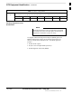
Table 1-3: Sector Configurations
7
6–Sector / 1–Carrier
The configuration below maps RX and TX with either bandpass filters or 2:1 cavity combiners for 6 sector / 1 carrier.
TX1 / RX1 TX2 / RX2 TX3 / RX3 TX4 / RX4 TX5 / RX5 TX6 / RX6 Carrier #
BBX2–1 BBX2–2 BBX2–3 BBX2–4 BBX2–5 BBX2–6 1
Ancillary Equipment Frame
identification
Equipment listed below can be wall mounted or mounted
in a standard 19” frame. The description assumes that all
equipment is mounted in a frame for clarity.
NOTE
If equipped with the RF Diagnostic Subsystem (RFDS) option, the
RFDS and directional couplers are the interface between the site
antennas, and the BTS or Modem frame. The RFDS equipment
includes:
the directional couplers
the (site receive bandpass/bandreject filters)
the RF Diagnostic Subsystem (RFDS).
1