
User Manual


Transmit & Receive Antenna VSWR – continued
PRELIMINARY 2
SC 4812ET BTS Optimization/ATP – CDMA LMF
July 1999
3-80
Equipment Setup – HP Test
Set
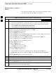
Follow the steps outlined in Table 3-46 to set up test equipment required
to measure and calculate the VSWR for each antenna.
Table 3-46: VSWR Measurement Procedure – HP 8921 Test Set
Step Action HP TEST SET
1 For manual VSWR testing, using external directional coupler, refer to Figure 3-25.
– Connect the communications test set RF OUT ONLY port to the INPUT port of the directional
coupler.
– Connect the RF IN/OUT port of the communication test set to the reverse (RVS) port on the
directional coupler. Terminate the forward port with a 50 ohm load.
– Install the antenna feed line to the output port on the directional coupler.
NOTE
Manual Communications Analyzer test setup (fields not indicated remain at default):
Set screen to RF GEN.
– Set RF Gen Freq to center frequency of actual CDMA carrier between 1930–1990 MHz for TX
and 1850–1910 MHz for RX.
– Set Amplitude to –30 dBm.
– Set Output Port to RF OUT.
– Set AFGen1 & AFGen2 to OFF.
2 Remove the antenna feed line and install an “RF short” onto the directional coupler output port.
NOTE
Set–up communication test set as follows (fields not indicated remain at default):
Set screen to SPEC ANL.
– Under Controls, set input port to ANT.
–
Set Ref Level to –40 dBm.
– Under Controls, select Main, select Auxiliary.
– Under Controls, select AV G . Set Avg = 20.
3 – Record the reference level on the communications analyzer and Note as P
S
for reference.
– Replace the short with the antenna feedline. Record the reference level on the communications
analyzer and Note for as P
A
reference.
– Record the difference of the two readings in dB.
4 Calculate the VSWR per the equation shown to the right.
Where:
R
L(
dB) = P
A
(dBm) – P
S
(dBm)
P
A = Power reflected from antenna
P
S = Power reflected from short
A calculated value of –13.98 dB equates to VSWR of better than 1.5:1.
VSWR
1 10
RL
20
1 – 10
RL
20
. . . continued on next page
3