
User Manual


Bay Level Offset Calibration – continued
July 1999
3-65
SC 4812ET BTS Optimization/ATP – CDMA LMF
PRELIMINARY 2
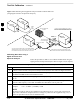
Test Equipment Setup:
RF Path Calibration
Follow the steps outlined in Table 3-35 to set up test equipment.
Table 3-35: Test Equipment Setup (RF Path Calibration)
Step Action
NOTE
Verify the GPIB is properly connected and turned on.
! CAUTION
To prevent damage to the test equipment, all transmit (TX) test connections must be via the 30 dB
directional coupler with a 20 dB in–line attenuator,
1 Connect the LMF computer terminal to the BTS LAN A connector on the BTS (if you have not
already done so). Refer to the procedure in Table 3–2 on page 3-8.
If required, calibrate the test equipment per the procedure in Table 3-28.
Connect the test equipment as shown in Figure 3-16 and Figure 3-17.
3