
User Manual


Test Set Calibration – continued
PRELIMINARY 2
SC 4812ET BTS Optimization/ATP – CDMA LMF
July 1999
3-58
50 OHM
TERMINATION
30 DB
DIRECTIONAL
COUPLER
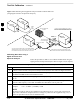
Figure 3-23: Calibrating Test Equipment Setup for TX BLO and TX ATP Tests
(using Signal Generator and Spectrum Analyzer)
Spectrum
Analyzer
Signal
Generator
A
Spectrum
Analyzer
40W NON–RADIATING
RF LOAD
B
SHORT TEST CABLE
Signal
Generator
THIS WILL BE THE CONNECTION TO THE HP8481A POWER
SENSOR DURING TX BAY LEVEL OFFSET TEST AND TO THE
PCS INTERFACE BOX INPUT PORT DURING TX ATP TESTS.
SHORT
TEST
CABLE THIS WILL BE THE CONNECTION TO THE TX
PORTS ON THE SC 4800/4800E DURING TX
BAY LEVEL OFFSET TEST AND TX ATP TESTS.
CABLE FROM 20 DB @ 20W ATTENUATOR TO THE
PCS INTERFACE OR THE HP8481A POWER SENSOR.
A
ONE 20DB 20 W IN
LINE ATTENUATOR
Calibrating RX Cables Using a
Signal Generator and
Spectrum Analyzer
Follow the procedure in Table 3-31 to calibrate the RX cables using the
signal generator and spectrum analyzer. Refer to Figure 3-24, if required.
Table 3-31: Calibrating RX Cables Using a Signal Generator and Spectrum Analyzer
Step Action
1 Connect a short test cable to the spectrum analyzer and connect the other end to the Signal Generator.
2 Set signal generator to –10 dBm at the customer’s RX frequency of 1750–1780 MHz for Korean PCS
and 1850–1910 MHz band for North American PCS.
3 Use spectrum analyzer to measure signal generator output (see Figure 3-24, “A”) and record the value
for “A”.
4 Connect the test setup, as shown in the lower portion of the diagram, to measure the output at the
customer’s RX frequency in the 1850–1910 MHz band. Record the value at point ‘‘B”.
5 Calibration factor = A – B
Example: Cal = –12 dBm – (–14 dBm) = 2 dB
NOTE
The short test cable is used for test equipment setup calibration only. It is not be part of the final test
setup. After calibration is completed, do not re-arrange any cables. Use the equipment setup, as is, to
ensure test procedures use the correct calibration factor.
3