
User Manual


Test Set Calibration – continued
PRELIMINARY 2
July 1999
3-53
SC 4812ET BTS Optimization/ATP – CDMA LMF
Automatically Selecting Test
Equipment in a Serial
Connection Tab
When using the auto-detection feature to select test equipment, the
CDMA LMF examines which test equipment items are actually
communicating with CDMA LMF. Follow the procedure in Table 3-25
to use the auto-detect feature.
Table 3-25: Selecting Test Equipment Using Auto-Detect
Step Action
1 From the Options menu, select LMF Options. The LMF Options window appears.
2 Click on Auto–Detection (if not enabled).
3 Type in the GPIB addresses in the box labeled GPIB address to search (if not already displayed).
NOTE
When both a power meter and analyzer are selected, the first item listed in the GPIB addresses to
search box will be used for RF power measurements (i.e., TX calibration). The address for a
power meter is normally 13 and the address for a CDMA analyzer is normally 18. If 13,18 is
included in the GPIB addresses to search box, the power meter (13) will be used for RF power
measurements. If the test equipment items are manually selected the CDMA analyzer is used only
if a power meter is not selected.
4 Click Apply. The button will darken until the selection has been committed. A check mark will
appear in the Manual Configuration section for detected test equipment items.
5 Click Dismiss to close the LMF Options window.
Network Test Equipment
Setup
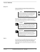
Test equipment can be remotely detected and used by CDMA LMF. A
LAN connection is required between the CDMA LMF location and the
test equipment location. A LAN-to-serial interface is required at the test
equipment location. A diagram of a typical network test equipment setup
is shown in Figure 3-22
Figure 3-22: Typical Network Test Equipment Setup
GPIB BOX
TEST
EQUIPMENT
LAN
CONNECTION
ETHERNET–
TO–SERIAL
TERMINAL
CDMA LMF
COMPUTER
ETHERNET
LAN ACCESS
NULL MODEM
SERIAL CABLE
GPIB
CABLE
CDMA LMF
LOCATION
TEST EQUIPMENT LOCATION
(FOR EXAMPLE, A CELL SITE)
FW00073
3