
User Manual


Test Equipment Set–up – continued
PRELIMINARY 2
SC 4812ET BTS Optimization/ATP – CDMA LMF
July 1999
3-42
Equipment Warm-up
Warm-up BTS equipment for a minimum of 60 minutes
prior to performing the BTS optimization procedure. This
assures BTS site stability and contributes to optimization
accuracy. (Time spent running initial power-up,
hardware/firmware audit, and BTS download counts as
warm-up time.)
IMPORTANT
*
Null Modem Cable
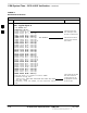
A null modem cable is required. It is connected between the LMF
COM1 port and the RS232–GPIB Interface box. Figure 3-14 shows the
wiring detail for the null modem cable.
Figure 3-14: Null Modem Cable Detail
5
3
2
7
8
1
4
6
5
2
3
7
8
1
4
6
GND
RX
TX
RTS
CTS
RSD/DCD
DTR
DSR
GND
TX
RX
RTS
CTS
RSD/DCD
DTR
DSR
ON BOTH CONNECTORS:
SHORT PINS 7 & 8;
SHORT PINS 1, 4, & 6
9–PIN D–FEMALE 9–PIN D–FEMALE
Test Equipment
The following test equipment is required to perform the tests:
LMF
CDMA Communications Test Set
Directional Coupler and Attenuator
RF Cables and connectors
Before installing any test equipment directly to any BTS
TX OUT connector, verify there are NO CDMA BBX
channels keyed. At active sites, have the OMC-R/CBSC
place the antenna (sector) assigned to the LPA under test
OOS. Failure to do so can result in serious personal injury
and/or equipment damage.
WARNING
To prevent damage to the test equipment, all transmit (TX)
test connections must be through the 30 dB directional
coupler and, for 1.9 GHz BTS, a 20 dB in-line attenuator.
CAUTION
3