
User Manual

UBS Equipment Identication Chapter 1: Introduction
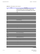
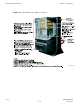
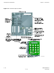
Figure 1 -5 UBS Site Span I/O P anel
SSI (fron t p anel)
CUST OMER
IP 13-24 OP 5-8
CUST OMER
IP 1-12 OP 1-4
37-Pin Connectors -
Con nect to Customer
IP/OP interconnect
equipment.
PSM 50-Pin Conne ctor -
Con nects to ALARM/CONTROL
Con nector on Optional PSM
Shelf front panel
RGPS 15 -Pin Connector -
Con nects to Optiona l
RGPS Head
SPAN 37-Pin Connector -
T1/E1 ba lanced Span I/O.
Con nects to BTS s ite span line
interconnect e quipment
-OR-
Optiona l E1 Unbalanced
Dau ghter Ca rd (S ee Detail A)
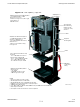
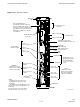
De tail A
Optional E1 Unbala nced Daughter Card
(SSI shown partially cut away)
Dau ghter Card
secured to SS I via
four corner sc rews.
37-Pin Connector on
bottom of c ard p lugs into
SSI SPAN connector
16 BNC Con nectors, 2 per
Span, RX a nd TX. Number
indicates Span Number
ti-cdma-05698.eps
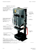
TREF OUT BNC Con nector -
Time reference output to te st eq uipment
FREF OUT BNC Connector -
Freq ue ncy re ference output
to te st equipment
EXT REF IN BNC Con nector -
External 10 MHz re ference input
for calibrating DMI OCXO
CRMS /LMT
CUST OMER ENE T -
RJ-45 Con nector
For conne ction of
LMF equip me nt
1 -22 68P09283A63 -5
FOA A UG 2007