
Product Card

1X UBS Macro B T S Optimization/A TP Acceptance T est Procedures - TX & RX
Before a FER test is run, be sure that the following is done:
All tr ansmitter connectors are properly terminated. T erminations should be 50 -Ohms,
200 W . F ailure to observ e these w arnings ma y result in bodily injury or equipment
damage.
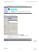
Procedure 4 -3 Setup T est Equipment — TX Output V erif y/Control T ests
1
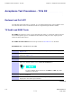
If it has not already been done, interface the LMF computer to the UBS .
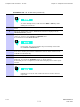
2
If it has not already been done, refer to Procedure 3-3 to start a GUI LMF
session and log into the UBS .
3
If it has not already been done, refer to Figure 3-23 , Figure 3-24 , Figure 3-25 ,
or Figure 3-26 as applicable, for the test equipment and antennas being used,
to connect test equipment for acceptance testing.
LMF -based measurements factor in TX cable loss between the UBS
and the test equipment.
Antenna Connectors
All acceptance testing requires test equipment connections to the UBS antenna TX or RX
connectors. Refer to the A TP T est Setup illustrations in the T est Equipment Set Up section of
Appendix E Optimization and Calibration Procedures for specific connection requirements
Recommended Tests
The recommended tests are TX Audit and Receive Signal Strength Indicator (RS SI) to confirm
the physical assembly of the frame and that all the cables TX, RX, Digital etc are correctly
connected. The rest of the tests are supported, optional, or for troubleshooting purposes.
TX/RX ATP Test Procedure
F ollow the procedure in Procedure 4 -4 to perform the All TX/RX A TP test.
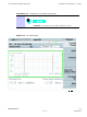
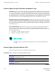
Procedure 4 -4 All TX/RX A TP T est Procedure
Continued
68P09283A63 -5 4 -9
FOA A UG 2007