
Product Card

Acceptance T est Procedures - TX & RX Chapter 4: Acceptance T est Procedures
Receive Signal Strength Indication Acceptance Test
Overview This test verifies Receive Signal Strength Indication (RS SI) for the selected sectors
to ensure integrity of the reverse (RX) path, that path losses are within tolerances required for
correct receiver operation, and correct installation of the RX path. T esting is performed using
the calibrated external test equipment as the signal source. The test equipment is controlled by
the LMF during the test. The receive signal generated by the test equipment is injected into the
sector RX path to be tested at the applicable UBS main and / or diversity receive ports.
Equipment Operation During T esting The LMF sets the pilot channel power level of the
sector for the selected sector to +XX dBm (measured at the TX port of the frame) and enables
the sector -carrier on pilot channel only to enable the RX circuitry . The LMF then commands the
test equipment to generate the receive signal on the selected carrier at -80 dBm as measured
at the UBS RX port
T est Measurements The power level of the received signal is measured by the RFX. The
LMF corrects the measured power of the signal using the RX BLO and determines if the
corrected signal gain is equal to or greater than the following specified criteria for the band in
which the UBS operates:
• 1900 MHz: –80 dBm ( -86 dBm or greater)
• 800 MHz: –80 dBm ( -86 dBm or greater)
The LMF provides -80 dBm signal (default) input to the UBS . The RS SI must be
+/ -6 dB.
Receive Signal Strength Indicator ATP
P erform the following procedure for RS SI acceptance testing.
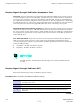
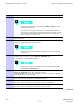
Procedure 4 -2 Procedure for RS SI Acceptance T esting
1
Set up the test equipment for RX acceptance tests. Reference Figure 3-23
through Figure 3-26 .
2
Select the carrier to be tested.
3
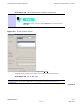
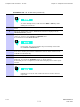
In the LMF window menu bar , click on T ests > RX > RS SI
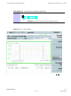
4
Select the carrier to be tested in the Channels/Carriers pick list which is
displayed.
Continued
4 -6 68P09283A63 -5
FOA A UG 2007