
Product Card


1X UBS Macro B T S Optimization/A TP Cable Calibr ation
Non–duplexed RX Cable Calibration
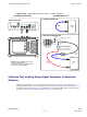
Procedure 3 -21 Calibr ating RX Cables Using a Signal Gener ator and Spectrum
Analyz er
1
Connect a short test cable to the spectrum analyzer and connect the other end to the Signal
Generator .
2
Set signal generator to -10 dBm at the customer’s RX frequency .
3
Use spectrum analyzer to measure signal generator output (see Figure 3-36 , A ) and record
the value for A.
4
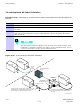
Connect the test setup, as shown in the lower portion of the diagram to measure the output at
the customer’s RX frequency . Record the value at Figure 3-36 , point B .
5
Calibration factor = A - B.
Example:
Cal = -12 dBm - (-14 dBm) = 2 dBm
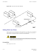
6
The short cable is used for
calibration only
. It is
not
part of the final test setup.
A fter calibration is completed,
do not
rearrange any cables. Use the equipment
setup as is to ensure test procedures use the correct calibration factor .
68P09283A63 -5 3 -71
FOA A UG 2007