
Product Card

Cable Calibr ation Chapter 3: LMF Oper ation
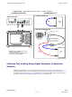
TX and Duplexed RX Cable Calibration
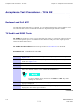
Procedure 3 -20 Calibr ating TX and Duplex ed RX Cables Using Signal Gener ator and Spectrum
Analyz er
1
Connect a short test cable between the spectrum analyzer and the signal generator .
2
Set signal generator to 0 dBm at the customer frequency .
3
Use a spectrum analyzer to measure signal generator output (see Figure 3-35 A ) and record
the value.
4
Connect the spectrum analyzer’s short cable to Figure 3-35 point B , (as shown in the lower
right portion of the diagram) to measure cable output at customer frequency . Record the
value at point B,
5
Calibration factor = A - B. Example: Cal = -1 dBm - (-53.5 dBm) = 52.5 dB
The short cable is used for calibration only . It is part of the final test setup. A fter
calibration is completed, rearrange any cables. Use the equipment setup, as is, to
ensure test procedures use the correct calibration factor .
Figure 3 -35 TX and Duplex ed RX Cable Calibr ation
50 OHM
TERMINATION
30 DB
DIRECTIONAL
COUPLER
SPECTRUM
ANALYZER
A
40W NON-RADIATING
RF LOAD
B
SHORT TEST CABLE
THIS WILL BE THE TX TEST CABLE CONNECTION TO THE
POWER SENSOR OR COMMUNICATIONS TEST SET INPUT
IPORT DURING TX CALIBRATION AND ATP TESTS.
SHORT
TEST
CABLE
CABLE FROM 10 DB MINIMUM @ 20W ATTENUATOR
TO THE POWER SENSOR OR COMMUNICATION
TEST SET.
10DB MINIMUM, 20 W
IN-LINE ATTENUATOR
SPECTRUM
ANALYZER
SIGNAL
GENERATOR
SIGNAL
GENERATOR
ti-cdma-00145.eps
3 -70 68P09283A63 -5
FOA A UG 2007