
Product Card
Cable Calibr ation Chapter 3: LMF Oper ation
Cable Calibration
■ ■ ■ ■ ■ ■ ■ ■ ■ ■ ■ ■ ■ ■ ■ ■ ■ ■ ■ ■ ■ ■ ■ ■ ■ ■ ■ ■ ■ ■ ■ ■ ■ ■ ■ ■ ■ ■ ■ ■ ■ ■ ■ ■ ■ ■ ■ ■ ■ ■ ■ ■ ■ ■ ■ ■ ■ ■ ■ ■ ■ ■
■
■
Calibrating Cables Overview
The cable calibration function measures the loss (in dB) for the TX and RX cables that are to be
used for testing. A CDMA analyzer is used to measure the loss of each cable configuration (TX
cable configuration and RX cable configuration). The cable calibration consists of the following:
• Measuring the loss of a short cable – This is required to compensate for any
measurement error of the analyzer . The short cable (used only for the calibration process)
is used in series with both the TX and RX cable configuration when measuring. The
measured loss of the short cable is deducted from the measured loss of the TX and RX
cable configuration to determine the actual loss of the TX and RX cable configurations.
The result is then adjusted out of both the TX and RX measurements to compensate for
the measured loss.
• Measuring the short cable plus the RX cable configuration loss – The RX cable
configuration normally consists only of a coax cable with type -N connectors that is long
enough to reach from the BTS RX port of the test equipment. Refer to Figure 3 -31 ,
Figure 3 -32 , Figure 3 -33 , or Figure 3 -34 for specific cable and connection requirements for
each type of communications system analyzer .
• Measuring the short cable plus the TX cable configuration loss – The TX cable
configuration normally consists of two coax cables with type N connectors and a directional
coupler , a load, and an additional attenuator (if required by the specified BTS). The total
loss of the path loss of the TX cable configuration must be as required for the BTS (normally
30 or 50 dB). Refer to Figure 3 -31 , Figure 3 -32 , Figure 3 -33 , or Figure 3 -34 for specific
cable and connection requirements for each type of communications system analyzer .
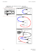
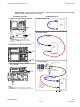
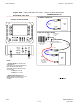
Cable Calibration Set–up Diagrams
Figure 3 -31 and Figure 3 -32 show the cable calibration set–up for various supported test sets.
The left side of the diagram depicts the location of the input and output connectors of each test
equipment item, and the right side details the set up for each test.
Calibrate Test Cabling using Communications System Analyzer
Cable Calibration is used to calibrate both TX and RX test cables.
3 -64 68P09283A63 -5
FOA A UG 2007