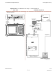
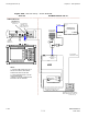
X UBS Macro BTS Optimization/ATP Test Equipment Set Up Figure 3-26 TX Calibration Test Setup – Anritsu MT8212B TEST SETS TRANSMIT (TX) SET UP ANRITSU MT8212B RF OUT 50 Ω COMMUNICATIONS SYSTEM ANALYZER 100-W ATT (MIN.) NON-RADIA TING RF LOAD SERIAL INTERFACE CONNECTOR RF IN 50 Ω RF IN 50 Ω SERIAL INTERFACE TX AND RX TEST CABLE 30 DB DIRECTIONAL COUPLER 50 Ω TERM.
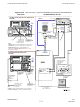
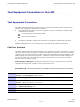
Test Equipment Set Up Chapter 3: LMF Operation Setup for ATP Figure 3-27, Figure 3-28, Figure 3-29, and Figure 3-30 show test set connections for ATP tests.
1X UBS Macro BTS Optimization/ATP Test Equipment Set Up Figure 3-27 ATP Test Setup – Agilent E4432B/8935 and Agilent E4432B/E4406A TEST SETS OPTIMIZATION/ATP SET UP AGILENT E4432B (TOP) AND 8935 SERIES E6380A (BOTTOM) RF OUTPUT 50 Ω TX/RX TEST CABLE RF OUTPUT 50 Ω SIGNAL GENERATOR 100-W ATT (MIN.) NON-RADIA TING RF LOAD RF IN/OUT OR RF INPUT 50 Ω DIRECTIONAL COUPLER (30 DB) RF IN/OUT GPIB COMMUNICATIONS SYSTEM ANALYZER EXT REF IN 50 Ω TERM.
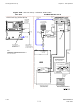
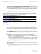
Test Equipment Set Up Figure 3-28 Chapter 3: LMF Operation ATP Test Setup – Advantest R3267/3562 TEST SETS OPTIMIZATION/ATP SET UP RF OUT 50 Ω TX/RX TEST CABLE Advantest R3267 (Top) and R3562 (Bottom) SIGNAL GENERATOR MOD TIME BASE IN TO EXT TRIG ON REAR OF SPECTRUM ANALYZER 100-W ATT (MIN.) NON-RADIA TING RF LOAD SYNTHE REF IN EXT TRIG IN GPIB SPECTRUM ANALYZER INPUT 50 Ω INPUT 50 Ω 10 MHZ OUT EXT TRIG BNC “T” DIRECTIONAL COUPLER (30 DB) 50 Ω TERM.
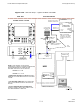
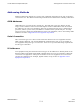
1X UBS Macro BTS Optimization/ATP Test Equipment Set Up Figure 3-29 ATP Test Setup – Agilent E7495A or E7495B ATP TEST SET UP TEST SET POWER METER AGILENT E7495A or E7495B (SEE NOTE FOR RX TEST ATTENUATION SELECTION) RX TEST PORT 1 RF OUT COMMUNICATIONS SYSTEM ANALYZER RF INPUT 50 Ω OR INPUT 50 Ω 100-W ATT (MIN.) NON-RADIA TING RF LOAD PORT 2 RF IN TX TEST 30 DB DIRECTIONAL COUPLER 50 Ω TERM. EVEN SECOND SYNC IN INTERNAL ETHERNET CARD NOTE: USE THE SAME CABLE SET FOR TX AND RX ATP.
Test Equipment Set Up Chapter 3: LMF Operation Figure 3-30 ATP Test Setup – Anritsu MT8212B TEST SET OPTIMIZATION/ATP SET UP ANRITSU MT8212B FREQ MONITOR 19.6608 MHZ CLOCK REFERENCE FROM SSI FREF OUT SYNC MONITOR EVEN SEC TICK PULSE REFERENCE FROM SSI TREF OUT RX TEST RF OUT 50 Ω COMMUNICATIONS SYSTEM ANALYZER 100-W ATT (MIN.
1X UBS Macro BTS Optimization/ATP Test Equipment Connection to the LMF Test Equipment Connection to the LMF ■ ■ ■ ■ ■ ■ ■ ■ ■ ■ ■ ■ ■ ■ ■ ■ ■ ■ ■ ■ ■ ■ ■ ■ ■ ■ ■ ■ ■ ■ ■ ■ ■ ■ ■ ■ ■ ■ ■ ■ ■ ■ ■ ■ ■ ■ ■ ■ ■ ■ ■ ■ ■ ■ ■ ■ ■ ■ ■ ■ ■ ■ ■ ■ Test Equipment Connection The LMF computer platform provides two types of hardware interfaces which support three different test equipment communication methods.
Test Equipment Connection to the LMF Chapter 3: LMF Operation Disconnecting and Reconnecting the LMF and the COM port - The LMF can be disconnected from the active COM port by using the Disconnect Port button in the GPIB/COM settings area of the Test Equipment tab. Disconnecting the LMF may be needed, for example, to use a HyperTerminal connection for a hardware Man Machine Interface (MMI) communication session. Perform the following to disconnect or reconnect the LMF and the selected COM port.
1X UBS Macro BTS Optimization/ATP Test Equipment Connection to the LMF Addressing Methods Different addressing methods are used for test equipment depending on the type of interface connection it has. The different addressing methods are described in the following subsections. GPIB Addresses GPIB addresses can range from 1 through 30. The LMF will accept any address in that range, but the numbers entered in the LMF Options window GPIB address box must match the addresses set in the test equipment.
Test Equipment Selection Chapter 3: LMF Operation Test Equipment Selection ■ ■ ■ ■ ■ ■ ■ ■ ■ ■ ■ ■ ■ ■ ■ ■ ■ ■ ■ ■ ■ ■ ■ ■ ■ ■ ■ ■ ■ ■ ■ ■ ■ ■ ■ ■ ■ ■ ■ ■ ■ ■ ■ ■ ■ ■ ■ ■ ■ ■ ■ ■ ■ ■ ■ ■ ■ ■ ■ ■ ■ ■ ■ ■ Test Equipment Selection Test equipment selection is performed in the LMF Options window, accessed through Tools > Options in the LMF window menu bar. The window has four tabs covering different categories of options.
1X UBS Macro BTS Optimization/ATP Test Equipment Selection GPIB Interface Test Equipment Manual Selection and Autodetection Prerequisites - The following must be done before performing these procedures: • LMF computer and test equipment are both correctly connected to the GPIB box • Test equipment is turned on • GPIB addresses set in the test equipment have been verified as correct using the applicable procedures in Appendix D Test Equipment Preparation.
Test Equipment Selection Chapter 3: LMF Operation Procedure 3-8 Manually Selecting Test Equipment - GPIB Interface (Continued) 8 Click the Apply button. The button will darken until the selection is committed. 9 Click the Detect on startup checkbox in the Autodetection settings area to allow the LMF to detect the test equipment automatically on application startup.A checkmark appears in the box. 10 Click the Save button to save the selection configuration for future LMF sessions.
1X UBS Macro BTS Optimization/ATP Procedure 3-9 6 Test Equipment Selection Autodetecting Test Equipment - GPIB Interface (Continued) If they are not already displayed, enter the GPIB address for each piece of required test equipment, separated by commas, in the GPIB Addresses: box in the GPIB Test equipment area.
Test Equipment Selection Chapter 3: LMF Operation Manual selection – Test equipment may be selected manually even if it is not connected to the LMF. Procedure 3-10 Manually Selecting Test Equipment - Serial Interface 1 In the LMF menu bar, select Tools > Options. Result: The LMF Options window appears. 2 Click on the Test Equipment tab (if not in the forefront). 3 Click the Serial radio button in the Connection Type area. Result: A black dot appears in the circle.
1X UBS Macro BTS Optimization/ATP Test Equipment Selection Procedure 3-11 Autodetecting Test Equipment - Serial Interface (Continued) 4 Click the COM radio button in the GPIB/COM settings area. Result: A black dot appears in the circle. 5 Select the correct LMF computer serial port from the Port: pick list (normally COM1) (Refer to the Test Equipment Connection to the LMF on page 3-45 section of this chapter).
Test Equipment Selection Chapter 3: LMF Operation Procedure 3-12 Manually Selecting Test Equipment - Network Interface (Continued) 4 In the Ethernet Test equipment area click the checkbox(es) of the test equipment being used. Result: Checkmarks appear in the box(es) clicked on. 5 If it is not already displayed, enter the IP address for the required piece test equipment in the IP box in the Ethernet Test equipment area. 6 Click the Apply button. The button will darken until the selection is committed.
1X UBS Macro BTS Optimization/ATP Test Set Calibration Test Set Calibration ■ ■ ■ ■ ■ ■ ■ ■ ■ ■ ■ ■ ■ ■ ■ ■ ■ ■ ■ ■ ■ ■ ■ ■ ■ ■ ■ ■ ■ ■ ■ ■ ■ ■ ■ ■ ■ ■ ■ ■ ■ ■ ■ ■ ■ ■ ■ ■ ■ ■ ■ ■ ■ ■ ■ ■ ■ ■ ■ ■ ■ ■ ■ ■ Test Set Calibration Background Proper test equipment calibration ensures that the test equipment and associated test cables do not introduce measurement errors, and that measurements are correct.
Test Set Calibration Chapter 3: LMF Operation Calibration Procedures Included Automatic Procedures included in this section use the LMF automated calibration routines to determine path losses of the supported communications analyzer, power meter, associated test cables, adapters, and (if used) antenna switch that make up the overall calibrated test equipment set. After calibration, the gain/loss offset values are stored in a test measurement offset file on the LMF computer.
1X UBS Macro BTS Optimization/ATP Test Set Calibration 1. The Agilent E4406A transmitter tester does not support power measurement level zeroing. Refer to the Test Equipment Calibration section of Appendix F for E4406A calibration. 2. Power measurement zeroing and other required calibration procedures for the Anritsu MT8212B are included in the Calibrating the Anritsu MT8212B on page 3-57 subsection below. Prerequisites • Test equipment to be zeroed has been connected correctly for tests to be run.
Test Set Calibration Chapter 3: LMF Operation Zero Out Power Meter Before using the MT8212B test set to perform RF power measurement, the test set internal power meter function must be zeroed. Prerequisites – The following must be done before the zeroing out the power meter: • The test set is connected to the LMF computer serial port with the Anritsu 800-441 RS-232 serial interface cable • Test equipment is turned on and has warmed up for at least 60 minutes.
1X UBS Macro BTS Optimization/ATP • Test Set Calibration Standard Open-Short-Load Components calibration: Anritsu 22N50 Open/Short, DC to 18 GHz, N(m) connector, 50 ohm Anritsu SM/PL precision load, DC-to-4 GHz, 42 dB, N(m) connector, 50 ohm • Standard InstaCal™ calibration: Anritsu ICN50 InstaCal calibration module, 2 MHz to 4 GHz, N(m) connector, 50 ohm TX analyzer calibration – Perform the following to calibrate the MT8212B TX analyzer function..
Test Set Calibration Chapter 3: LMF Operation Prerequisites - The following must be done before the CW generator calibration: • The test set is connected to the LMF computer serial port with the Anritsu 800-441 RS-232 serial interface cable • Test equipment is turned on and has warmed up for at least 60 minutes.
1X UBS Macro BTS Optimization/ATP Test Set Calibration Procedure 3-17 Anritsu MT8212B Multi-function Test Set CW Generator Calibration (Continued) 8 Click on OK to close the status report window.
Setting and Editing Generator Calibration Data Chapter 3: LMF Operation Setting and Editing Generator Calibration Data ■ ■ ■ ■ ■ ■ ■ ■ ■ ■ ■ ■ ■ ■ ■ ■ ■ ■ ■ ■ ■ ■ ■ ■ ■ ■ ■ ■ ■ ■ ■ ■ ■ ■ ■ ■ ■ ■ ■ ■ ■ ■ ■ ■ ■ ■ ■ ■ ■ ■ ■ ■ ■ ■ ■ ■ ■ ■ ■ ■ ■ ■ ■ ■ Generator Calibration Data Generator calibration data is automatically stored in a generator calibration data file by the LMF when the generator function of a test equipment item is calibrated using t
1X UBS Macro BTS Optimization/ATP Setting and Editing Generator Calibration Data Procedure 3-18 Set or Edit Generator Calibration Data (Continued) For Frequency Band fields, select the required frequency band from the dropdown provided. Selections are made available for the BTS which the LMF is logged into. 5 To delete a row, click in the row, and then click the Delete Row button. 6 For each tab with changes, click the Save button to save the displayed values.
Cable Calibration Chapter 3: LMF Operation Cable Calibration ■ ■ ■ ■ ■ ■ ■ ■ ■ ■ ■ ■ ■ ■ ■ ■ ■ ■ ■ ■ ■ ■ ■ ■ ■ ■ ■ ■ ■ ■ ■ ■ ■ ■ ■ ■ ■ ■ ■ ■ ■ ■ ■ ■ ■ ■ ■ ■ ■ ■ ■ ■ ■ ■ ■ ■ ■ ■ ■ ■ ■ ■ ■ ■ Calibrating Cables Overview The cable calibration function measures the loss (in dB) for the TX and RX cables that are to be used for testing.
1X UBS Macro BTS Optimization/ATP Cable Calibration Prerequisites Ensure the following prerequisites have been met before proceeding: • One of the following: LMF computer serial port and test equipment are connected to the GPIB box For MT8212B, the test equipment is connected to the LMF computer serial port For E7495A/B, the LMF computer NIC and the E7495 are connected to the Ethernet hub (Test Equipment Connection section) • Test equipment is turned on and has warmed up for at least 60 minutes.
Cable Calibration Chapter 3: LMF Operation Figure 3-31 Cable Calibration Test Setup – Agilent 8935 CALIBRATION SET UP SUPPORTED TEST SETS A. SHORT CABLE CAL HEWLETT-P ACKARD MODEL HP 8935 SHORT CABLE ANT IN DUPLEX OUT TEST SET B. RX TEST SETUP N-N FEMALE ADAPTER RX CABLE SHORT CABLE TEST SET C. TX TEST SETUP 50 Ω TERM.
1X UBS Macro BTS Optimization/ATP Cable Calibration Figure 3-32 Cable Calibration Test Setup – Advantest R3267/R3562,E4406A/E4432B, and Agilent E4432/8935 Series E6380A SUPPORTED TEST SETS CALIBRATION SET UP ADVANTEST R3267 (TOP) AND R3562 (BOTTOM) A. SHORT CABLE CAL SHORT CABLE TEST SET RF IN B.
Cable Calibration Chapter 3: LMF Operation Figure 3-33 Cable Calibration Test Setup – Agilent E7495A and E7495B CALIBRATION SET UP SUPPORTED TEST SETS A. SHORT CABLE CAL AGILENT E7495A OR E7495B 10 DB PAD SHORT CABLE TEST SET 10 DB PAD B. RX and TX TEST SETUP 50 Ω TERM.
1X UBS Macro BTS Optimization/ATP Cable Calibration Figure 3-34 Cable Calibration Test Setup – Anritsu MT8212B SUPPORTED TEST SETS CALIBRATION SET UP A. SHORT CABLE CAL ANRITSU MT8212B SHORT CABLE RF IN 50 Ω TEST SET RF OUT 50 Ω C. RX and TX TEST SETUP 50 Ω TERM. 100-W ATT (MIN.
Cable Calibration Chapter 3: LMF Operation TX and Duplexed RX Cable Calibration Procedure 3-20 Calibrating TX and Duplexed RX Cables Using Signal Generator and Spectrum Analyzer 1 Connect a short test cable between the spectrum analyzer and the signal generator. 2 Set signal generator to 0 dBm at the customer frequency. 3 Use a spectrum analyzer to measure signal generator output (see Figure 3-35 A) and record the value.
1X UBS Macro BTS Optimization/ATP Cable Calibration Non–duplexed RX Cable Calibration Procedure 3-21 Calibrating RX Cables Using a Signal Generator and Spectrum Analyzer 1 Connect a short test cable to the spectrum analyzer and connect the other end to the Signal Generator. 2 Set signal generator to -10 dBm at the customer’s RX frequency. 3 Use spectrum analyzer to measure signal generator output (see Figure 3-36, A) and record the value for A.
Cable Calibration Chapter 3: LMF Operation Figure 3-36 Non-Duplex RX Cable Calibration SIGNAL GENERATOR SIGNAL GENERATOR SPECTRUM ANALYZER A SHORT TEST CABLE CONNECTION TO THE COMMUNICATION TEST SET OUTPUT PORT DURING RX MEASUREMENTS. SPECTRUM ANALYZER SHORT TEST CABLE BULLET CONNECTOR B LONG CABLE 2 CONNECTION TO THE RX PORTS DURING RX MEASUREMENTS. ti-cdma-06209.
1X UBS Macro BTS Optimization/ATP Cable Calibration Procedure Perform the following to set cable loss values. Procedure 3-22 Setting Cable Loss Values 1 In the LMF menu bar, click on Util > Edit > Cable Loss 2 In the data entry pop–up window, select one of the following: • TX Cable Loss • RX Cable Loss 3 To add a new channel number, click on Add Row, and click in Channel# and Loss (dBm) columns and enter the desired values.
Cable Calibration Chapter 3: LMF Operation 3-74 68P09283A63-5 FOA AUG 2007
Chapter 4 Acceptance Test Procedures ■ ■ ■ ■ ■ ■ ■ ■ ■ ■ ■ ■ ■ ■ ■ ■ ■ ■ ■ ■ ■ ■ ■ ■ ■ ■ ■ ■ ■ ■ ■ ■ ■ ■ ■ ■ ■ ■ ■ ■ ■ ■ ■ ■ ■ ■ ■ ■ ■ ■ ■ ■ ■ ■ ■ ■ ■ ■ ■ ■ ■ ■ ■ ■ ■ ■ 68P09283A63-5 AUG 2007 4-1 FOA
Introduction to ATP Chapter 4: Acceptance Test Procedures Introduction to ATP ■ ■ ■ ■ ■ ■ ■ ■ ■ ■ ■ ■ ■ ■ ■ ■ ■ ■ ■ ■ ■ ■ ■ ■ ■ ■ ■ ■ ■ ■ ■ ■ ■ ■ ■ ■ ■ ■ ■ ■ ■ ■ ■ ■ ■ ■ ■ ■ ■ ■ ■ ■ ■ ■ ■ ■ ■ ■ ■ ■ ■ ■ ■ ■ Introduction General The Acceptance Test Procedures (ATP) allow Cellular Field Engineers (CFEs) to run automated acceptance tests on all UBS subsystem devices equipped in the NEC using the LMF and the test equipment it supports.
1X UBS Macro BTS Optimization/ATP Introduction to ATP Test Equipment Set Calibration Refer to Test Set Calibration on page 3-55,Cable Calibration on page 3-64, and Appendix D Test Equipment Preparation for detailed interconnection information needed for calibrating equipment, cables, and other test equipment set components. Equipment has been factory-tested for FCC compliance. If license-governing bodies require documentation supporting UBS site compliance with regulations, a full ATP may be necessary.
Acceptance Test Procedures - TX & RX Chapter 4: Acceptance Test Procedures Acceptance Test Procedures - TX & RX ■ ■ ■ ■ ■ ■ ■ ■ ■ ■ ■ ■ ■ ■ ■ ■ ■ ■ ■ ■ ■ ■ ■ ■ ■ ■ ■ ■ ■ ■ ■ ■ ■ ■ ■ ■ ■ ■ ■ ■ ■ ■ ■ ■ ■ ■ ■ ■ ■ ■ ■ ■ ■ ■ ■ ■ ■ ■ ■ ■ ■ ■ ■ ■ Reduced and Full ATP The full ATP (all the ATP tests) is optional. It is recommended that the reduced ATP be used. The reduced ATP consists of TX Audit and Receive Signal Strength Indicator (RSSI).
1X UBS Macro BTS Optimization/ATP Acceptance Test Procedures - TX & RX Procedure 4-1 Procedure for TX Audit (Continued) 8 Click Save Results or Dismiss button. If Dismiss is selected, the test results will not be saved. Figure 4-1 TX Audit Signal ti-cdma-TX_Audit.
Acceptance Test Procedures - TX & RX Chapter 4: Acceptance Test Procedures Receive Signal Strength Indication Acceptance Test Overview This test verifies Receive Signal Strength Indication (RSSI) for the selected sectors to ensure integrity of the reverse (RX) path, that path losses are within tolerances required for correct receiver operation, and correct installation of the RX path. Testing is performed using the calibrated external test equipment as the signal source.
1X UBS Macro BTS Optimization/ATP Acceptance Test Procedures - TX & RX Procedure 4-2 Procedure for RSSI Acceptance Testing (Continued) 5 Select the RX Branch to be tested from the choices in the drop down list provided (Both, Main, Diversity) 6 Enter the appropriate power level into the Generator amplitude box (default: -80 dBm) 7 Click OK. A status bar will be displayed followed by a Directions pop up window.
Acceptance Test Procedures - TX & RX Chapter 4: Acceptance Test Procedures Required Test Equipment The following test equipment is required: • LMF • Power Meter • Communications System Analyzer • Before connecting any test equipment directly to any UBS TX OUT connector, verify that there are no CDMA channels keyed. • At active sites, have the OMC-R operator place the carrier assigned to the UBS under test OOS. Failure to do so can result in serious personal injury and/or equipment damage.
1X UBS Macro BTS Optimization/ATP Acceptance Test Procedures - TX & RX Before a FER test is run, be sure that the following is done: All transmitter connectors are properly terminated. Terminations should be 50-Ohms, 200 W. Failure to observe these warnings may result in bodily injury or equipment damage. Procedure 4-3 Setup Test Equipment — TX Output Verify/Control Tests 1 If it has not already been done, interface the LMF computer to the UBS.
Acceptance Test Procedures - TX & RX Chapter 4: Acceptance Test Procedures 1 Set up the test equipment for abbreviated tests per Procedure 4-3 2 Select the device(s) to be tested. To select multiple items, hold down the Shift or Ctrl key while making the selections. For all TX tests except Code domain, a SectorCarrier must be selected. For code domain select the modem and carrier. For RX test — FER select the modem and SectorCarrier. For RX test — RSSI select SectorCarrier only.
1X UBS Macro BTS Optimization/ATP Acceptance Test Procedures - TX & RX Procedure 4-4 All TX/RX ATP Test Procedure (Continued) 10 Click on Save Results or Dismiss. If Dismiss is used, the test results will not be saved in the test report file. Figure 4-2 TX Test Options Screen en ter_filena me_her e_and_mo ve_per_st ep_8 Perform the procedure in Procedure 4-5 for all-inclusive transmit test.
Acceptance Test Procedures - TX & RX Procedure 4-5 2 Chapter 4: Acceptance Test Procedures All TX ATP Test (Continued) On LMF, select devices to be tested. To select multiple items, hold down the Shift or Ctrl key while making the selections. 3 Click on Tests in the BTS Menu bar, and select All TX ATP... from pull-down menu. 4 Select the appropriate carrier (HDModem) from those displayed in the Channels/Carrier pick list.