
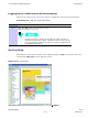
Product Card
T est Equipment Set Up Chapter 3: LMF Oper ation
Test Equipment Set Up
■ ■ ■ ■ ■ ■ ■ ■ ■ ■ ■ ■ ■ ■ ■ ■ ■ ■ ■ ■ ■ ■ ■ ■ ■ ■ ■ ■ ■ ■ ■ ■ ■ ■ ■ ■ ■ ■ ■ ■ ■ ■ ■ ■ ■ ■ ■ ■ ■ ■ ■ ■ ■ ■ ■ ■ ■ ■ ■ ■ ■ ■
■
■
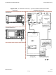
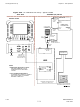
Connecting Test Equipment to the UBS
The following equipment is required to perform optimization:
• LMF
• Communications system analyzer model supported by the LMF
• Non -radiating transmit line termination load
• Directional coupler and in -line attenuator
• RF cables and connectors
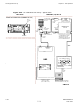
• Null modem cable (see Figure 1 -1 )
• GPIB interface box
The following figures provide representative illustrations of connections for test equipment
currently supported by the LMF :
• Figure 3 -23 , Figure 3 -24 , Figure 3 -25 , and Figure 3 -26 show the test set connections
for TX calibration.
• Figure 3 -27 , Figure 3 -28 , Figure 3 -29 , and Figure 3 -30 show test set connections for
optimization/A TP tests.
• Figure 3 -31 , Figure 3 -32 , Figure 3 -33 , or Figure 3 -34 illustrate cable calibration test set–up.
Test Equipment GPIB Address Settings
All test equipment except the Agilent E7495A and
Anritsu
MT8212B is controlled by the LMF
through an IEEE -488/GPIB bus. T o communicate on the bus, each piece of test equipment must
have a GPIB address set which the LMF will recognize. The standard address settings used by
the LMF for the various types of test equipment items are as follows:
• Signal generator address: 1
• P ower meter address: 13
• Communications system analyzer: 18
Using the procedures included in the Setting GPIB Addresses section of Appendix D T est
Equipment Preparation , verify and, if necessary , change the GPIB address of each piece of test
equipment used to match the above.
3 -32 68P09283A63 -5
FOA A UG 2007